Hinged Light-Trap Panel¶
1. Purpose¶
TBS-001 requires a light-tight seal at the cargo door end of the container that simultaneously allows personnel access during operation without admitting daylight. The hinged light-trap panel fills both roles: it seals the full 2,362 × 2,388mm cargo door opening as a rigid structural panel, and incorporates a revolving drum light trap that permits operators to enter and exit the darkened interior at any time without opening the panel or breaking the light seal. In case of emergency, or to easy loading and unloading of materials, the whole hinged panel can open fully, being locked from the inside.
Sheet 1 — Front Elevation (1:20): Panel Dimensions, Drum, Hinges, Latches (interior face)
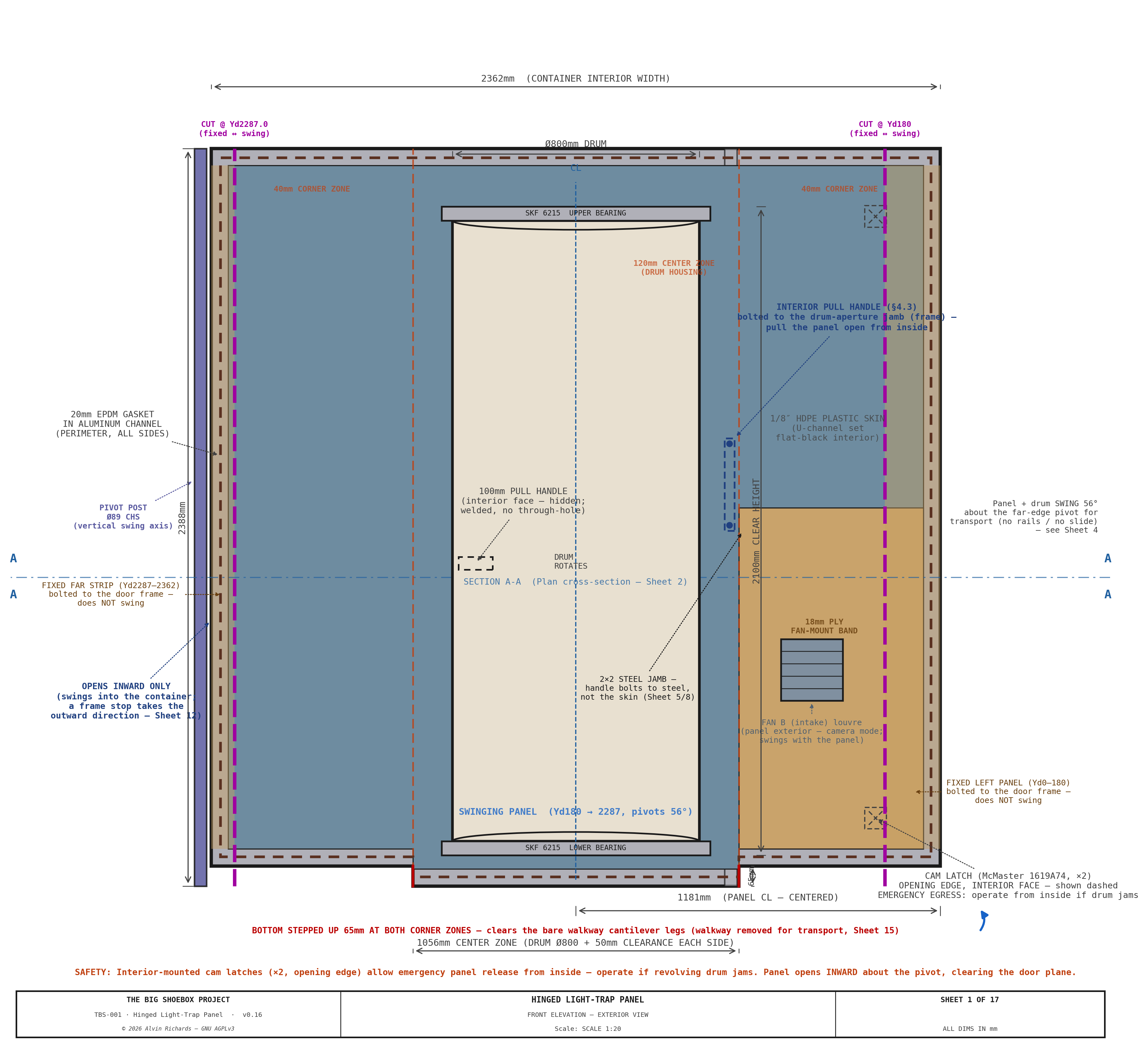
Design goals:
- 100% light exclusion — no straight-line optical path from exterior to interior
- Single-operator personnel access at any time during exposure
- Inward swing (into the container, about the Ø89 pivot) for full-width loading access (IBC totes, equipment) — the panel opens inward only; a frame stop takes the outward direction
- ~56° transport swing about the Ø89 pivot post — carries the B2 punch-out bay inboard of the ISO container doors (clears the closed-door inner face by +29mm) + hardware
- Emergency egress operable from inside without tools
- Weatherproof for outdoor field deployment (IP44 rated seals)
- Single-person mode conversion (~5 minutes)
Interactive 3D model — the revolving light-trap drum, hinged stepped panel, Ø89 swing pivot, fixed door frame, and Fan B. Drag to orbit, scroll to zoom.
2. Panel Construction¶
2.1 Stepped Profile¶
The panel has three thickness zones to accommodate the revolving drum in the center while keeping the corners flush with the container walls.
Sheet 2 — Plan Cross-Section (1:10 horiz / 1:1 depth): Housed Revolving Door — Housing, Drum & Light-Tight Geometry
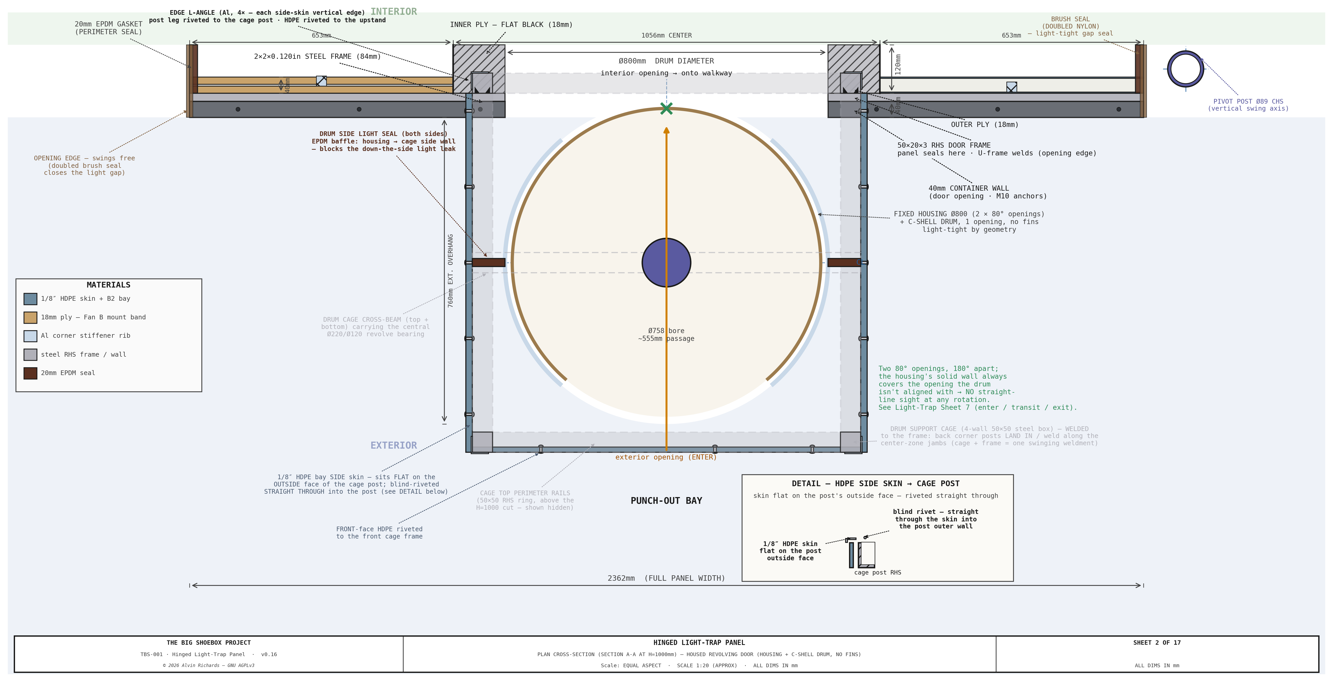
| Zone | Width (mm) | Thickness (mm) | Construction | |------|--------------|-----------|---------------|-------------| | Near corner | 653 | 40 | 1/8" HDPE skin + 1"×1"×⅛" 6061 Al stiffener grid + 1/8" HDPE skin (40mm framed); 18mm-ply Fan-B mount band bottom→1,225mm | | Center | 1,056 | 120 | 1/8" HDPE skin + 84mm RHS frame + 1/8" HDPE skin | | Far corner | 653 | 40 | 1/8" HDPE skin + 1"×1"×⅛" 6061 Al stiffener grid + 1/8" HDPE skin (40mm framed) |
The 80mm step between corner and center zones to locate the light-trap housing; the corner zones are flush-faced panels that seal against the fixed door frame.
2.2 Frame¶
| Parameter | Value |
|---|---|
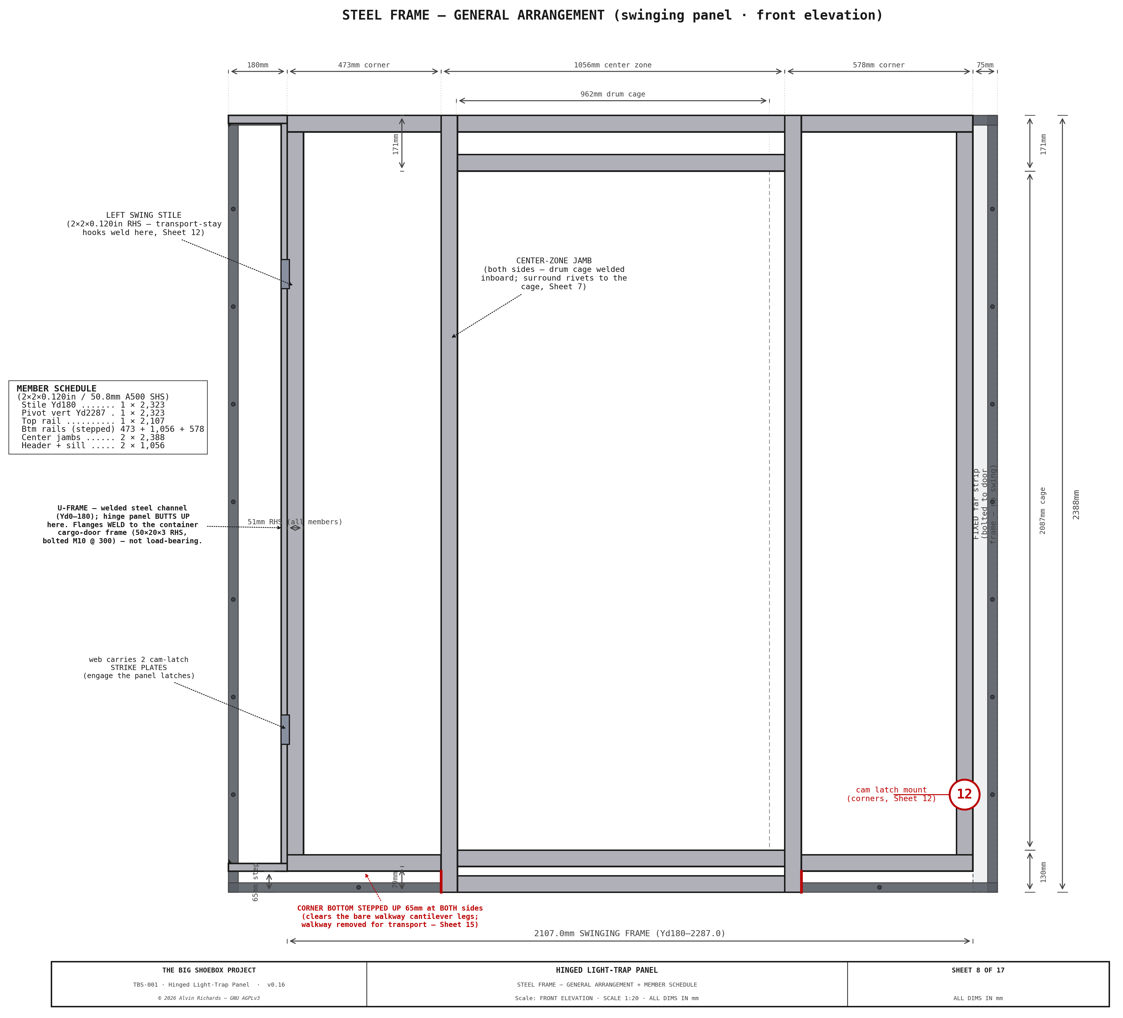
| Frame material | 50 × 50 × 3mm RHS mild steel |
| Outer dimensions | 2,362 × 2,388mm |
| Skin (each face) | 1/8" HDPE plastic sheet (same material as the drum/housing), set in U-channels — black-pigmented, light-tight, moisture/chemical-proof. Exception: an 18mm exterior-grade plywood band on the Fan B corner (bottom up to 1,225mm) for rigid fan/duct mounting + screw retention |
| Interior finish | Black-pigmented sheet (HDPE) + flat-black touch-in — optically dead at visible wavelengths |
| Frame perimeter | Welded corners, mitered joints |
| Panel weight (full panel: skins + Ø800 housing + B2 bay, excl. drum) | ~139 kg (first-principles: 96 kg framed skins + 22 kg housing + 21 kg B2 bay). See §2.4–2.5 for the movable breakdown + trade study |
Sheet 8 — Steel Frame General Arrangement (interior front elevation): member sizes, weld schedule, corner detail
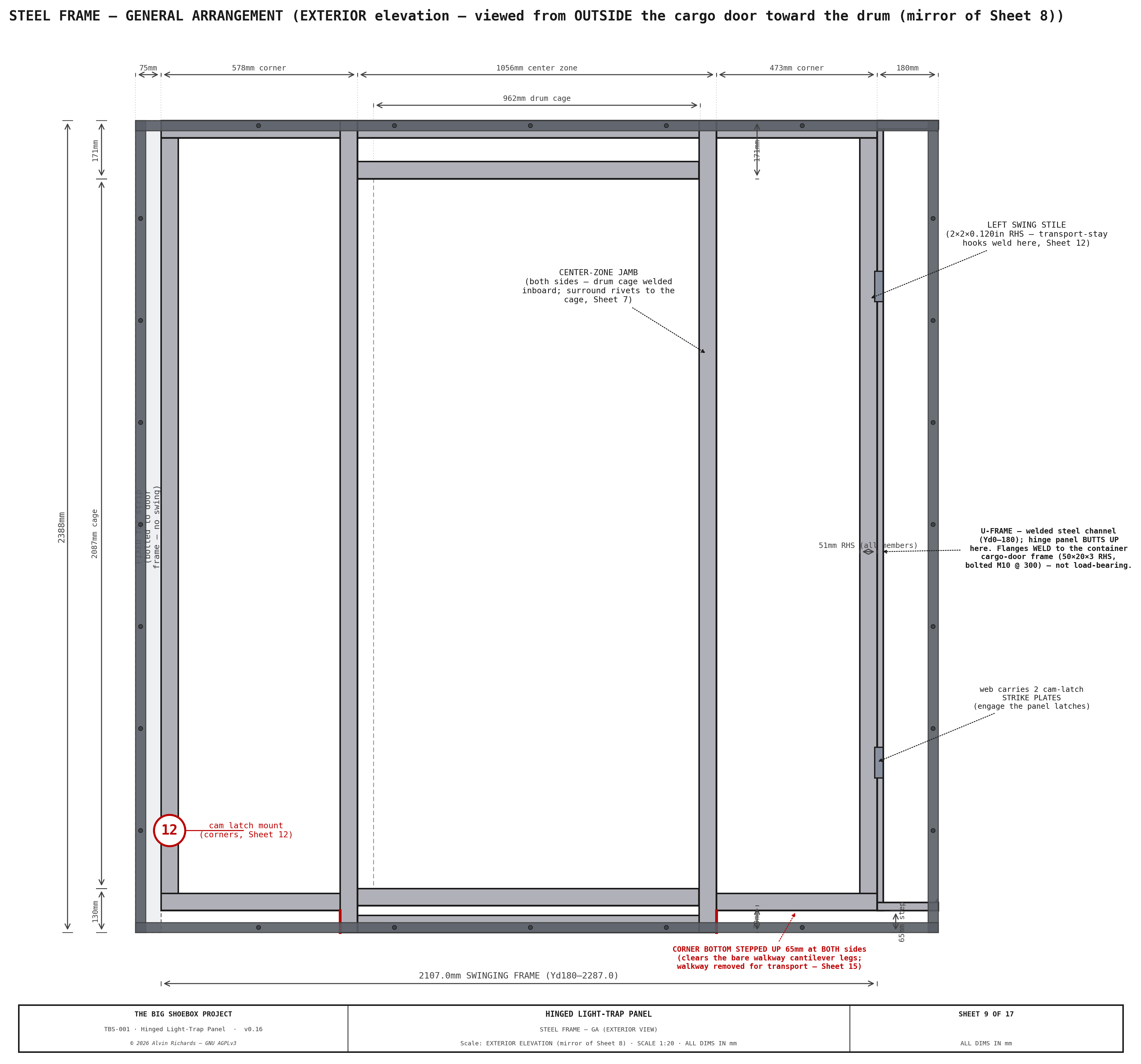
Sheet 9 — Steel Frame General Arrangement (exterior mirror): fastener/hardware face
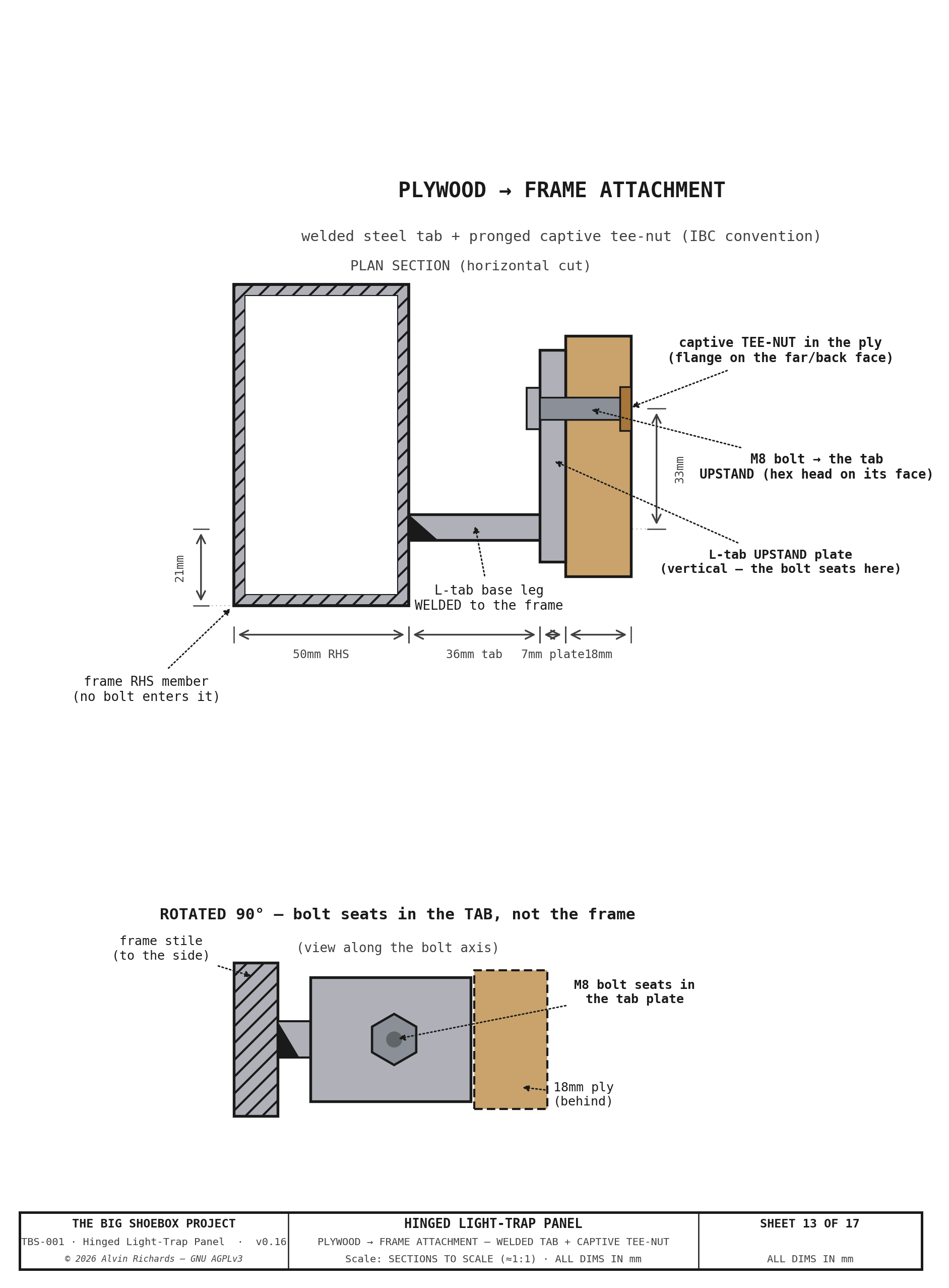
Sheet 13 — Plywood → Frame Attachment (enlarged): welded tab + captive tee-nut
2.3 Perimeter Seals¶
A 20mm closed-cell EPDM compression gasket runs the two vertical edges of the panel, seated in an extruded aluminum channel, and compresses against the fixed welded door frame (50 × 50 × 3mm RHS) when the two opening-edge cam latches engage. The top and bottom edges are nylon strip-brush light seals instead (§6, paths #3/#4): because the panel edge sweeps sideways through the seal as it swings, a brush passes the edge through cleanly where a compression EPDM would drag and deform. Together they give a light-tight seal on all four sides.
A second 20mm EPDM gasket — the housing-surround seal — runs as a ring around the Ø800 light-trap housing aperture. Because the housing is fixed (only the drum rotates inside it), this gasket seals the fixed surround to the frame independently of the moving panel, all the way around the opening the housing passes through. It sits in the same exterior door plane, concentric inboard of the panel-perimeter seal (see §6, light-path #8).
2.4 Movable-Panel Weight Breakdown¶
The transport scheme swings the panel + drum ~56° about the vertical Ø89 pivot, so
the movable assembly is everything that rotates about that pivot. The breakdown
below is first-principles from the geometry constants (reproducible via
src/generators/generate_movable_panel_weight.py); it isolates the swing zone
and deducts the Ø800 housing aperture from the center skins, so it
is slightly lower than the whole-panel figure carried in the
Weight Distribution Report §3.2.
| Group | Component | Construction | kg |
|---|---|---|---|
| A · Skins + frame | Fan B mount band | 18mm ply, 0.47m × 0.99m, 2 faces | 10.2 |
| HDPE corner skins | 1/8" HDPE (near above band + far) | 12.3 | |
| Corner Al stiffener grid | 1×1×1/8 6061 angle | 2.8 | |
| Center RHS frame | 2×2×0.120in steel SHS, 11.1m | 49.2 | |
| HDPE center skins | 1/8" HDPE, Ø800 aperture deducted | 11.4 | |
| A subtotal | 85.9 | ||
| B · Housing | HDPE shell + steel flange/hub | Ø800×3/16", two 80° openings | 21.8 |
| C · Drum | HDPE C-shell (1/8") + 8mm Al caps + Ø75 shafts + 2× SKF 6215 + stiffeners + pull handle | Ø764 | 35.9 |
| D · Bay | B2 punch-out bay walls | 1/8" HDPE, 4-wall tube 0.89m deep | 20.8 |
| E · Cage | Drum support cage frame | ~25×25×3 angle, 16.1m box | 16.1 |
| F · Seals | Vertical perimeter + housing EPDM + top/bottom strip brush + drum wipers | 20mm foam + strip/felt brush | 2.7 |
| G · Latches | Cam latches (2) | ~0.5 kg each | 1.0 |
| H · Pivot (rotating) | Thrust/journal bearings + collar/hub | carries leaf at pivot | 13.0 |
| MOVABLE TOTAL (carried-rotating) | ≈197 | ||
| + transport-only locks (stays + 4 saddles) | engaged only when swung | +10 |
By material: steel 103 kg (52%), HDPE 79 kg (40%), aluminum 3 kg (1.4%), plywood 10 kg (5%, Fan B band only), EPDM/other 3 kg. (All light-lock plastic — skins, drum, bay, housing — is now one weld-compatible HDPE.)
Findings. The largest remaining single item is the steel center RHS frame (49 kg) — the structural spine carrying the drum — which is the only meaningful target left (§2.5). Because the swing axis is vertical, this mass produces no gravity overturning torque at any swing angle; it matters for the thrust-bearing/pivot-post sizing, for handling during assembly (still beyond a two-person lift — an engine crane or gantry hoist is required), and for total container payload.
2.5 Weight-Reduction¶
Black-pigmented HDPE is light-tight (proven on the drum), moisture- and chemical-proof in the wet darkroom, and floats in its channel to absorb its higher thermal expansion. A tighter stiffener- channel grid (~400–450mm centers) keeps the floppier 1/8" sheet flat at the EPDM seal line. One exception: the Fan B corner keeps an 18mm plywood band (bottom up to 1,225mm) for rigid fan/duct mounting + screw retention. The panel sits at ~139 kg. The HDPE skin + 1"×1"×⅛" Al stiffener grid + U-channel envelope is moisture/chemical-proof, light-tight, and weld-sealed (same material and weld process as the drum/housing); it costs more than a plywood build (§8.1).
Sheet 11 — Fan-B Mount Band: Fabrication (fan cutout, fan/duct bolt pattern, frame-tab tee-nut holes)
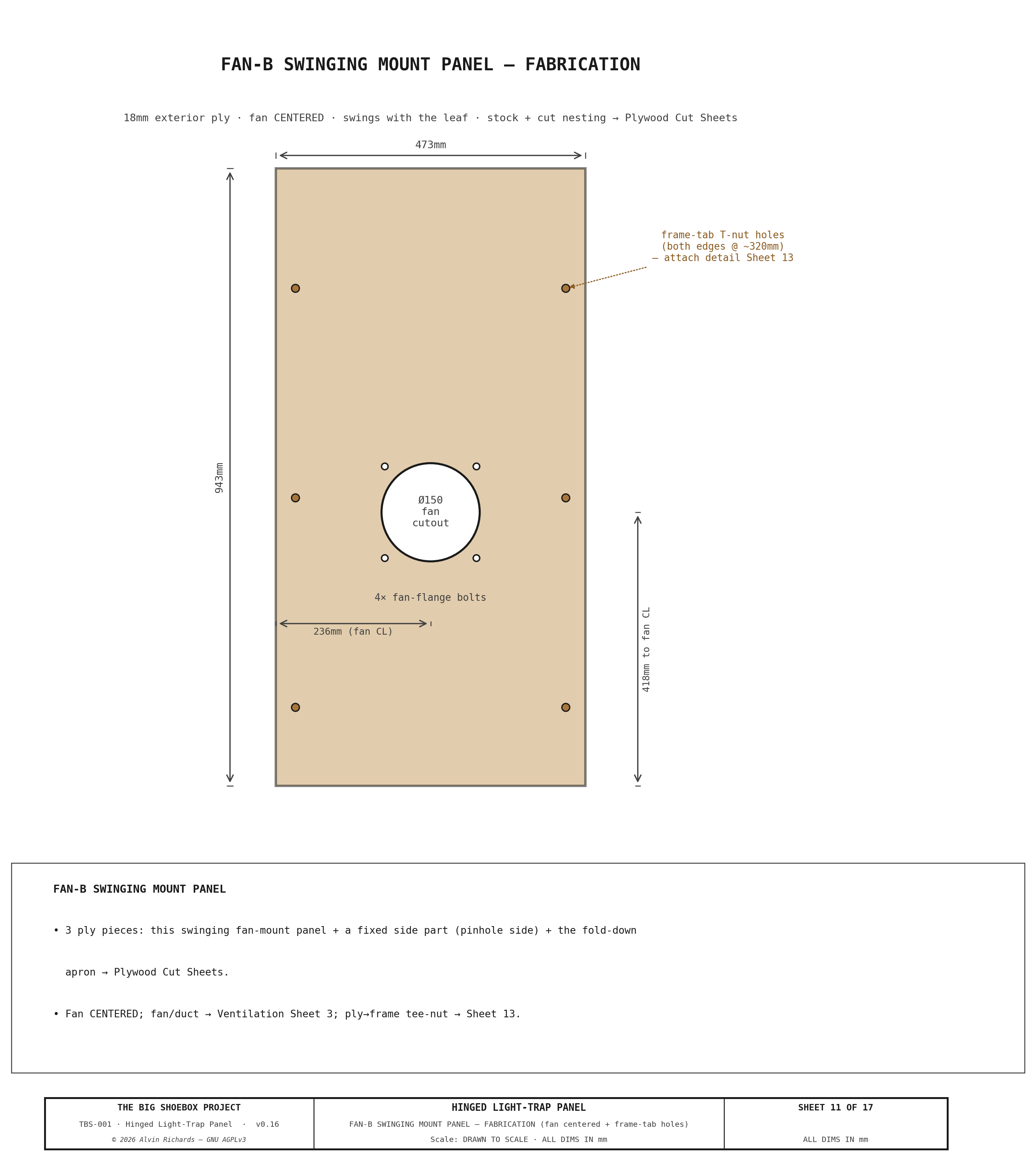
The band's plywood stock and cut nesting are single-sourced on the Plywood Cut Sheets — it is cut, with the corridor and pinhole-wall panels, from the shared 18mm exterior sheets rather than a dedicated sheet.
2.6 HDPE Surround Fabrication¶
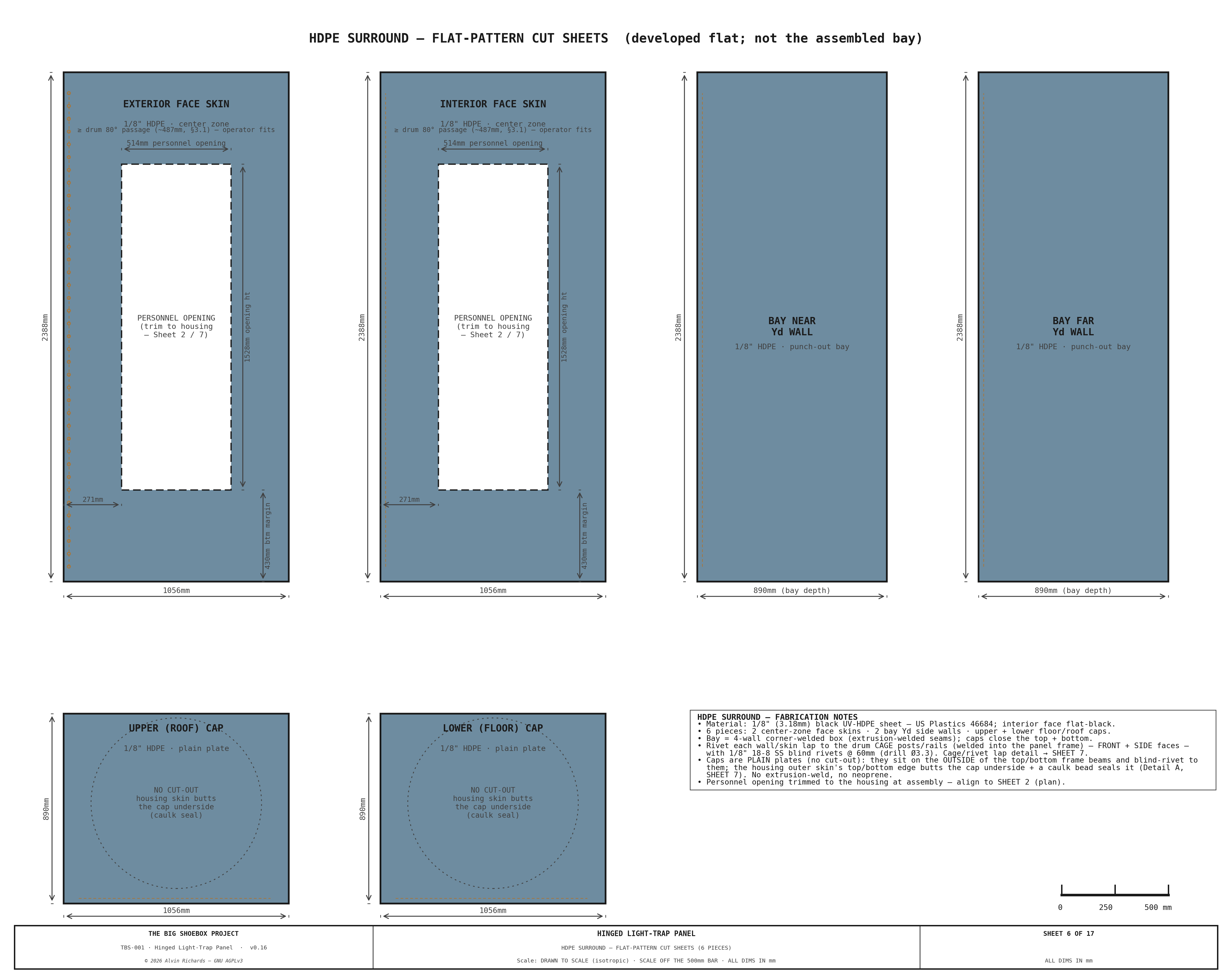
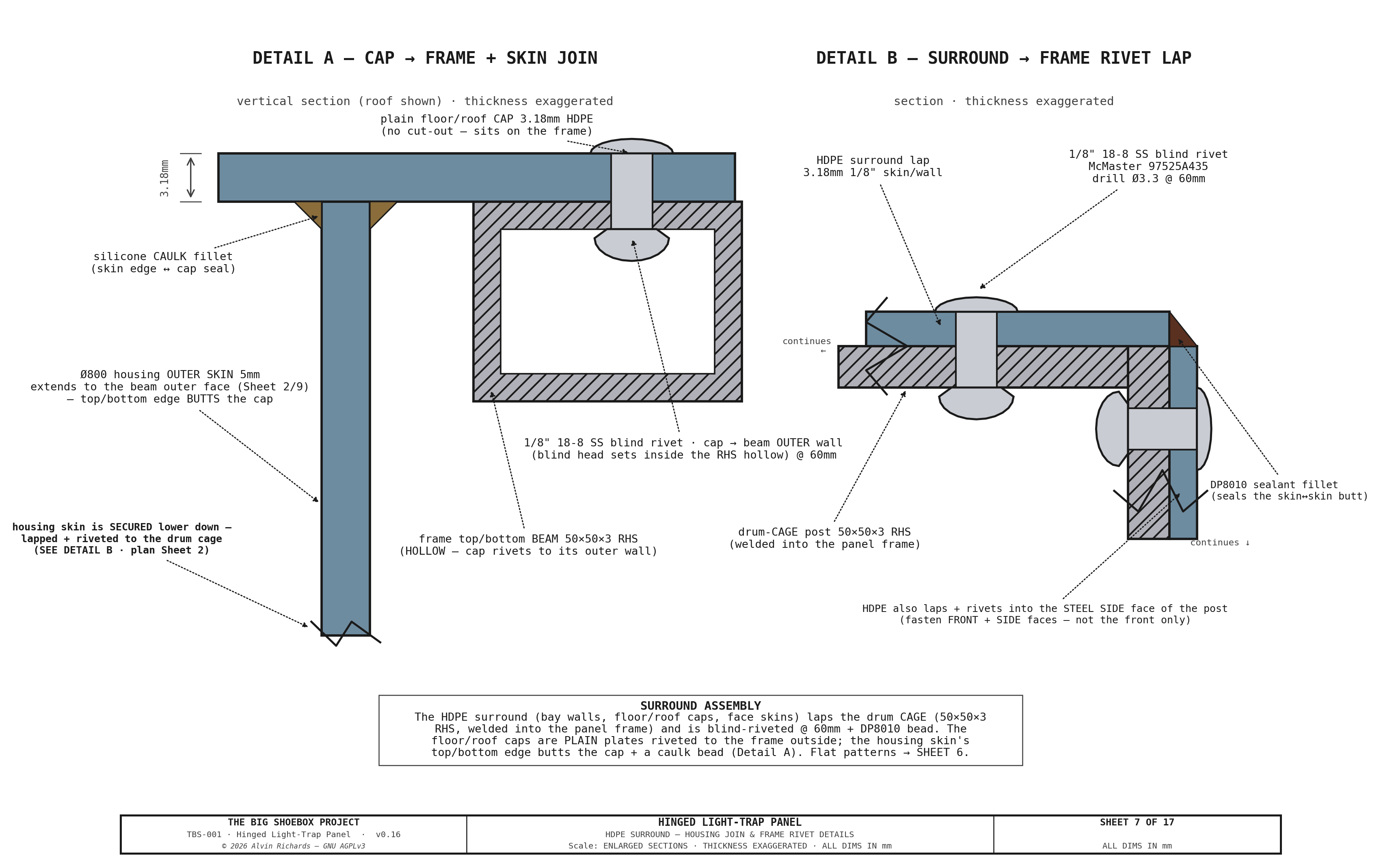
The center-zone HDPE surround — the skin that wraps the Ø800 light-trap housing and the forward B2 punch-out bay — is a corner-welded 1/8" HDPE assembly of six pieces: the two center-zone panel-face skins (carrying the personnel light-lock opening), the two bay side walls, and the upper and lower floor/roof caps. The caps are plain plates (no cut-out): each sits on the outside of the top/bottom frame beams and blind-rivets to them. The Ø800 housing outer skin extends to the beam outer faces (see the Light Trap Selection Sheet 9), and its top/bottom edge butts the cap underside, sealed by a silicone caulk bead (no weld, no neoprene). The surround is fastened to the drum cage (50×50×3 RHS) by a lapped, blind-riveted joint — the HDPE laps the cage posts/rails (front + side faces) and is set with 1/8" 18-8 stainless blind rivets on a regular pitch, with a DP8010 sealant bead along the lap for light-tightness. Because the cage is welded into the panel top/bottom rails (one weldment), riveting to the cage ties the surround to the panel structure — it is not a floating skin. The same rivet family is used on the light-trap shell.
The flat-pattern cut sheets for all six pieces are Sheet 6; the housing-join and frame-rivet lap sections are Sheet 7. The housing cut geometry is shared with the Light Trap Selection housing sheet so the surround↔housing interface stays single-sourced.
Sheet 6 — HDPE Surround Flat-Pattern Cut Sheets (6 pieces)
Sheet 7 — HDPE Surround: Housing Join & Frame Rivet Details
3. Housed Revolving-Door Light Lock¶
The light lock is a fixed cylindrical housing + single-opening C-shell drum — the standard commercial-darkroom-door arrangement — sized for a single operator.
Sheet 3 — Drum Vertical Section Elevation (Section A-A): Walking-height orientation confirmation + Details B & C (panel bottom & top light seals)
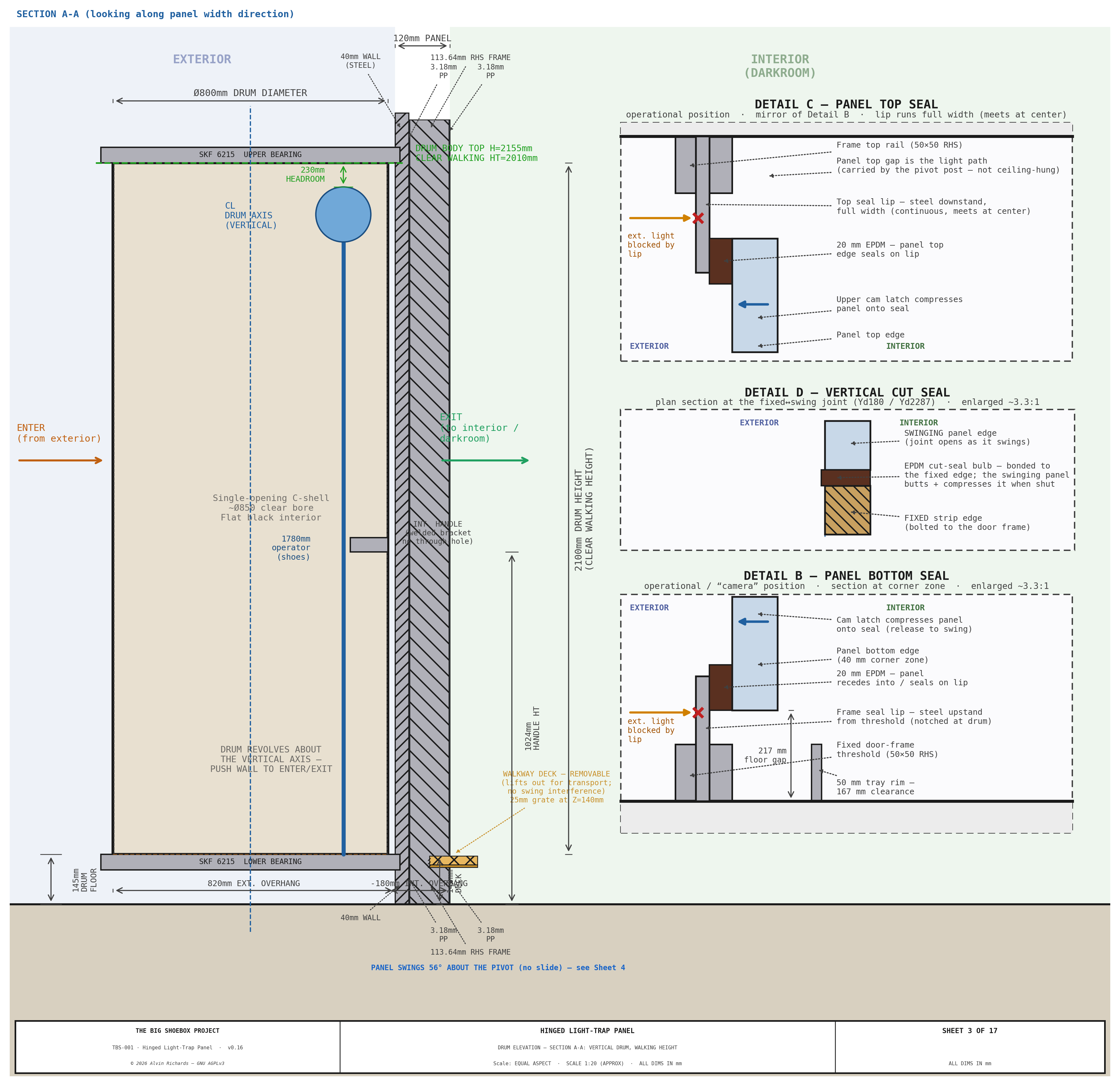
3.1 Specification¶
| Parameter | Value |
|---|---|
| Type | Fixed cylindrical housing + single-opening C-shell revolving drum (no internal fins) |
| Housing outer diameter | Ø800mm (fixed, built into the panel center zone) |
| Housing openings | Two, 80° arc each, 180° apart — one facing exterior, one facing the interior/walkway |
| Drum (rotating) | Ø764mm C-shell, single 80° opening, ~Ø758mm clear bore |
| Passage width | ~487mm (the 80° opening) — single operator, sideways entry |
| Height | Cap top at 2,100mm AFF (cage/beam top 2,217mm); see Light Trap Selection §3 |
| Mounting | Carried with the panel — panel bottom rides at the 217mm floor gap; the drum-cage underside hangs clear of the fixed floor-leg walkway posts + tray rim as it swings. Operator steps up from the walkway deck into the drum. |
| Wall thickness | 5mm (3/16in) UV-HDPE housing (LT_HOUSING_T) + 1/8" HDPE drum (LT_DRUM_T) — rolled and extrusion-welded plastic skin; opening edge-stiffened |
| Interior finish | Black-pigmented sheet + flat-black touch-in at welds (no etch-prime) |
| Exterior finish | UV-stabilized black/gray sheet — inherent, no primer |
| Clear walking height | 1,883mm clear interior |
| Internal baffles | None — light-tightness is by the fixed-housing geometry (§3.3) |
| Weight | housing ~22 kg + rotating drum ~36 kg = ~58 kg (plastic skin, ≈59% of the 3mm-aluminum ~99 kg; the steel shaft/bearings set a floor the shell mass can't drop below) |
3.2 Bearings¶
| Item | Specification |
|---|---|
| Bearing model (×2) | SKF 6215-2RS1 sealed deep-groove ball bearing |
| Bore | 75mm ID, 130mm OD, 25mm wide |
| Clearance | C3 |
| Radial load rating | 52.7 kN (basic dynamic C) |
| Operating temperature | 0–120°C |
| Stub shafts | 75mm Ø × 150mm steel, bolted through an isolated steel hub to the aluminum drum caps (dissimilar-metal joint) |
| Axial retention | Circlip on stub shaft each side |
| Upper mount | Aluminum housing top ring bolted to panel top rail (6 × M10 SS, nylon-isolated) |
| Lower mount | Steel floor collar bolted to panel bottom rail (8 × M10 SS) — no weld |
| Bearing housing height | 45mm (each) |
3.3 Light Path Verification¶
The light lock is light-tight by geometry. The fixed housing has two openings (one facing the exterior, one facing the interior/walkway), each 80° of arc and 180° apart; the rotating drum is a C-shell with a single 80° opening and no internal fins. Because each opening is narrower than 90° and the two housing openings are 180° apart, the drum opening can never align with both at once — the housing's solid wall always covers whichever opening the drum opening is not facing. So at no rotation angle is there a straight-line path from exterior to interior: daylight entering the bore through the exterior opening is stopped by the drum's solid wall before it can reach the interior opening.
See Light Trap Selection §5 and Light-Trap Sheet 7 (enter / transit / exit verification).
3.4 Drum Seals¶
| Location | Seal method |
|---|---|
| Top | 12mm closed-cell neoprene wiper ring bonded to drum top cap + silicone bead against ceiling mount plate |
| Bottom | 12mm closed-cell neoprene wiper ring bonded to drum bottom cap + silicone bead against floor mount plate |
| Drum↔housing rotating seal | Felt/brush wiper strips on the two vertical edges of the drum opening sweep against the housing inner wall as the drum turns, blocking light leaking around the opening; top + bottom felt wiper rings close the ~15mm annular running gap |
| Housing-to-panel gap (top/bottom caps) | The floor/roof caps are plain plates riveted to the outside of the top/bottom frame beams; the housing outer skin extends to the beam outer faces and its top/bottom edge butts the cap underside, closed by a silicone caulk bead — no weld, no neoprene (Sheet 7 Detail A) |
| Weather rating | IP44 (splash and rain protection) |
3.5 Handle¶
An off-the-shelf 12″ (308mm) round pull handle (McMaster 1871A65, Ø0.5″ bar, 2.06″ standoff) is mounted on the interior face at 900mm height. It bolts (1/4″ screws) to a steel stile that spans and bolts to the two aluminum caps — no welds, and no through-bolt penetration of the drum wall on the exterior face, so the pull load lands in the structural caps and no light leak path is created. The operator enters by pushing the bare exterior drum wall, then uses the interior pull handle to pull the drum closed and brace during exit.
3.6 Access & Light-Tightness Verification (both tests pass)¶
Light-lock access & light-tightness verification (see Light-Trap Sheet 7)
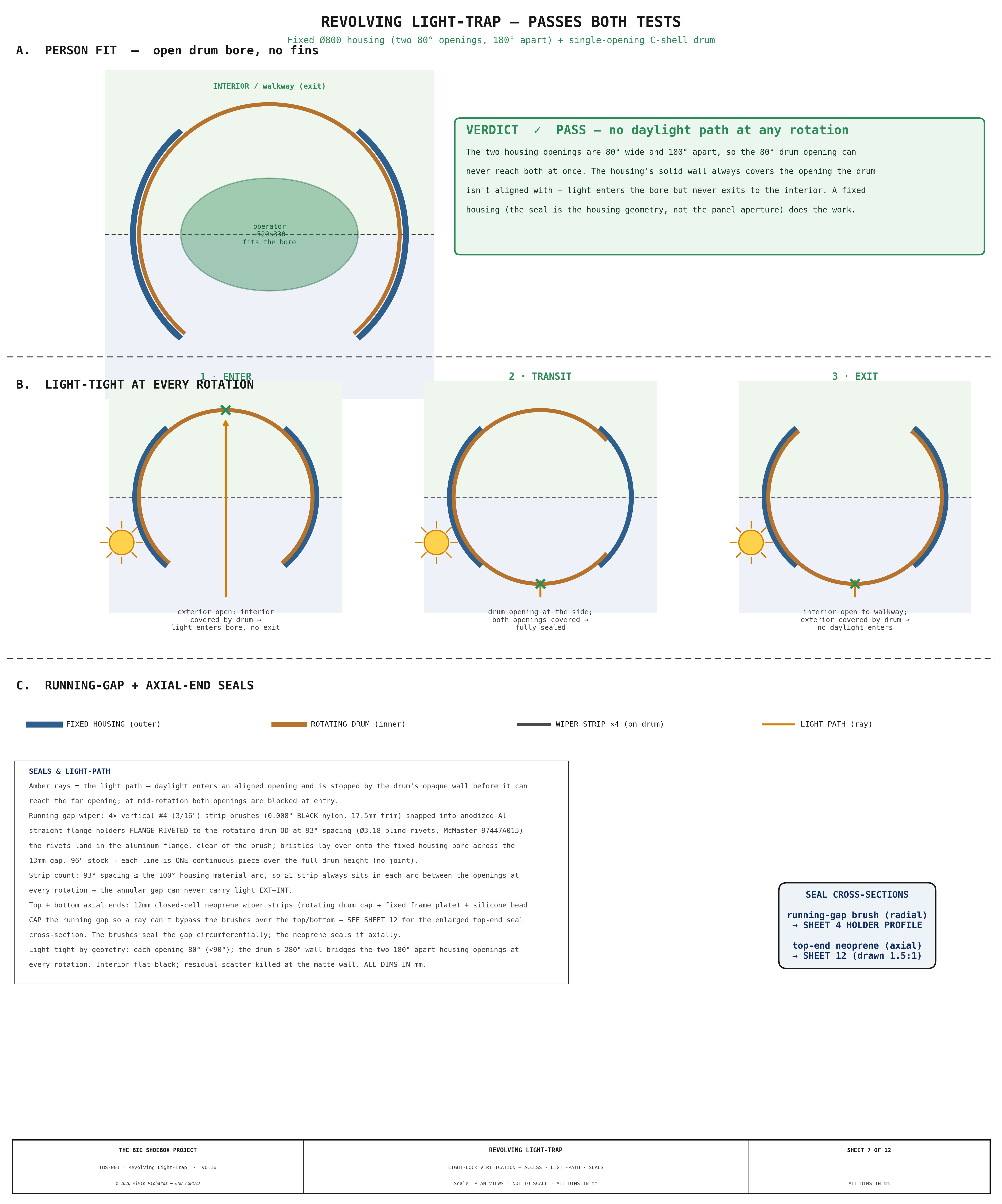
1. Does a person fit? — Yes. The drum is a single-opening C-shell, so the whole ~Ø758mm bore is clear standing space. The 80° opening gives a ~487mm passage (sideways entry), enough for a single operator to enter and turn inside. Emergency egress remains the whole panel swinging open.
2. As the drum rotates, can daylight enter? — No. The fixed housing's two 80° openings are 180° apart, so the 80° drum opening can never reach both at once: at enter the exterior opening feeds the bore but the interior opening is covered by the drum's solid wall; at transit both housing openings are covered; at exit the exterior opening is covered. There is no straight-line path at any angle.
4. Hinges and Latches¶
4.1 Hinges¶
| Parameter | Value |
|---|---|
| Type | Vertical Ø89×8 CHS pivot post (the reused film-plane far-left upright) on a thrust collar + top/bottom hub bearings — STRUCTURAL SIGN-OFF REQUIRED |
| Quantity | 1 post (carries the full bay + housing + drum swing cantilever, ~3.6 kN·m, SF ~3.7 in S355) |
| Position | Far-left panel edge |
| Mounting | Post fixed top + bottom to the container end structure; the swinging frame rotates on the hub bearings (vertical axis ⇒ balanced at any angle, no gravity torque) |
| Swing | ~56° inboard to the transport position (locked by the top + bottom wall stays); swings clear of the door plane for personnel/equipment access |
The plastic-skinned drum/housing (LT_DRUM_T = 1/8" HDPE, LT_HOUSING_T = 5mm (3/16in) UV-HDPE) keeps the added mass modest. Because the pivot axis is vertical, the assembly is balanced at any swing angle — no gravity torque and no free-edge sag, so no swing-support caster is needed. The pivot post and its bearing + weld pattern require a structural engineer's sign-off before fabrication.
4.2 Cam Latches¶
| Parameter | Value |
|---|---|
| Model | McMaster 1619A74 lift-and-turn cam latch |
| Quantity | 2 (both on the opening/free edge — top + bottom) |
| Positions | 210mm from the opening edge; 220mm and 2,168mm from floor (the pivot edge is hinged and needs no latch — a frame stop takes the outward direction) |
| Mounting face | Interior — deliberate safety design for emergency egress |
| Seal compression | Compresses EPDM perimeter gasket against fixed door frame |
Emergency egress: If the revolving drum jams and prevents normal egress, an operator inside the container can release both interior-mounted cam latches independently and push the panel open inward — it swings into the container about the Ø89 pivot, clearing the door plane so the operator can step out. (The panel opens inward only; a stop on the fixed frame takes the outward direction — §4.2 latches.)
4.3 Interior Pull Handle¶
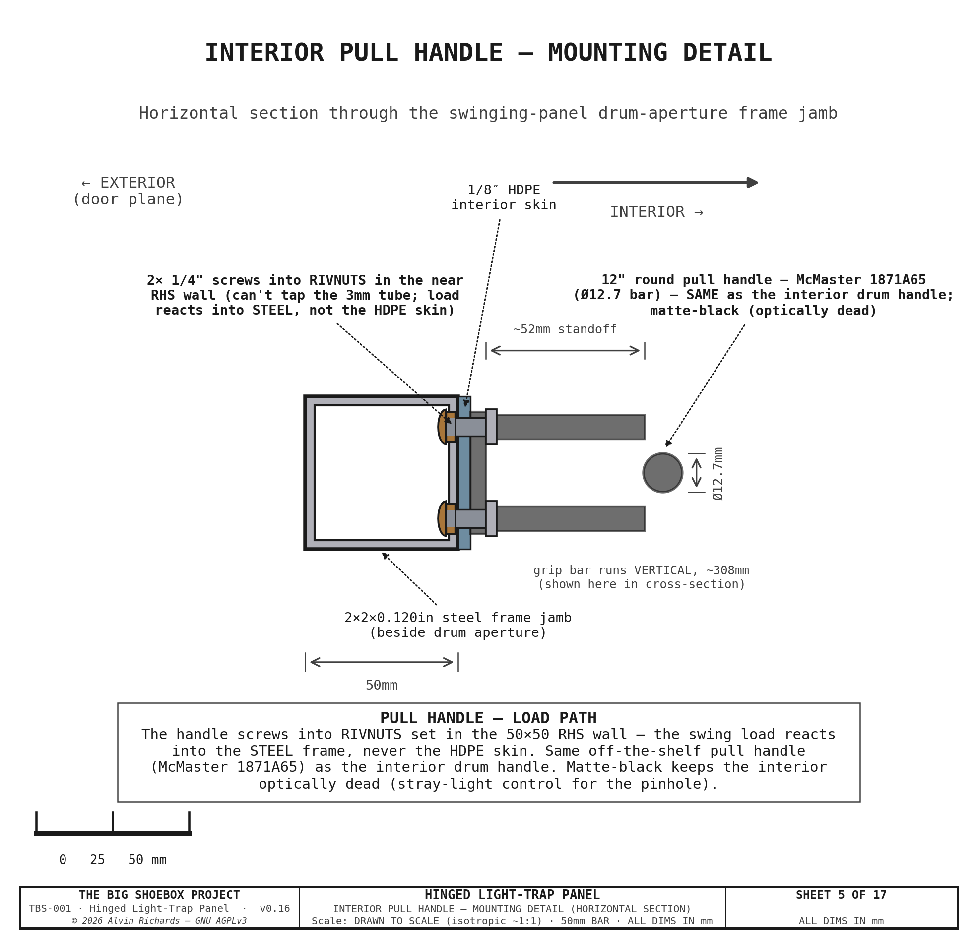
A grab/pull handle is through-bolted to the panel's structural frame on the interior face — the left jamb of the drum aperture, at waist height — so a single operator can grip it and swing the heavy (~139 kg movable) panel open from inside the container, both for the emergency-egress swing (§4.2) and to initiate the transport rotation (§5). It bolts to the steel frame, not the HDPE skin. This is the panel-swing handle — distinct from the drum-rotation pull handle inside the revolving light lock (owned by the Light Trap Selection set); the two handles serve different mechanisms and are drawn on their own blueprints.
| Parameter | Value |
|---|---|
| Type | McMaster 1871A65 round pull handle (Ø12.7 bar, ~308mm grip, 52mm standoff) — the same off-the-shelf part as the interior drum handle |
| Mounting | Screwed into 1/4"-20 rivet-nuts set in the near wall of the 50 × 50 × 3mm RHS frame jamb — the swing load reacts into the steel frame, not the HDPE skin (rivnuts because the 3mm tube wall can't be tapped and there is no back-access to a nut) |
| Position | Interior face of the swinging panel, on the left drum-aperture jamb. The transport swing pivots on the far edge (§5), so this near-of-center jamb keeps the operator's leverage while landing the load on frame steel right beside the drum (rather than the unbacked HDPE skin) |
| Finish | Matte-black powder-coat — the interior must stay optically dead (stray-light control for the pinhole), so the handle is not left bare/reflective |
See §8.1 for the part; the handle is also shown on the interior-face Sheet 1 front elevation.
Sheet 5 — Interior Pull Handle: mounting detail (handle through-bolted to the RHS frame)
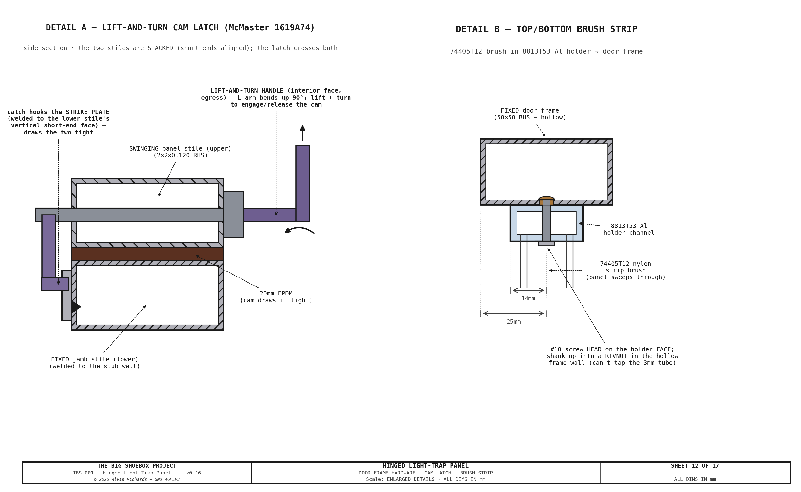
Sheet 12 — Door-Frame Hardware: cam-latch keeper + brush-strip holder (two details) — the transport lock formerly here is now on its own focused sheet (Sheet 17).
5. Rotating Transport System¶
For transport the entire swinging assembly — the panel center section, the B2 punch-out bay, and the housing + revolving drum — revolves ~56° about a vertical Ø89mm CHS pivot post (the reused film-plane far-left upright at the far panel edge). The swing carries the bay's ~890mm exterior overhang from outside the cargo-door plane to inboard of it, so the ISO doors close.
Two narrow strips stay fixed at the door plane and do not swing: the near strip and the far strip. The cargo doors close outboard of the fixed near strip.
To let the swinging cage cross the film-plane rail line, the two left film rails (top-left + bottom-left) lift out of their drop-in saddles and the left walkway + door-end near-deck section lift out before the swing; all are re-seated to datum afterward.
5.1 Panel Positions¶
Sheet 4 — Rotating transport + swing clearance: panel swings 56° about the pivot (camera vs swung), removable left rails
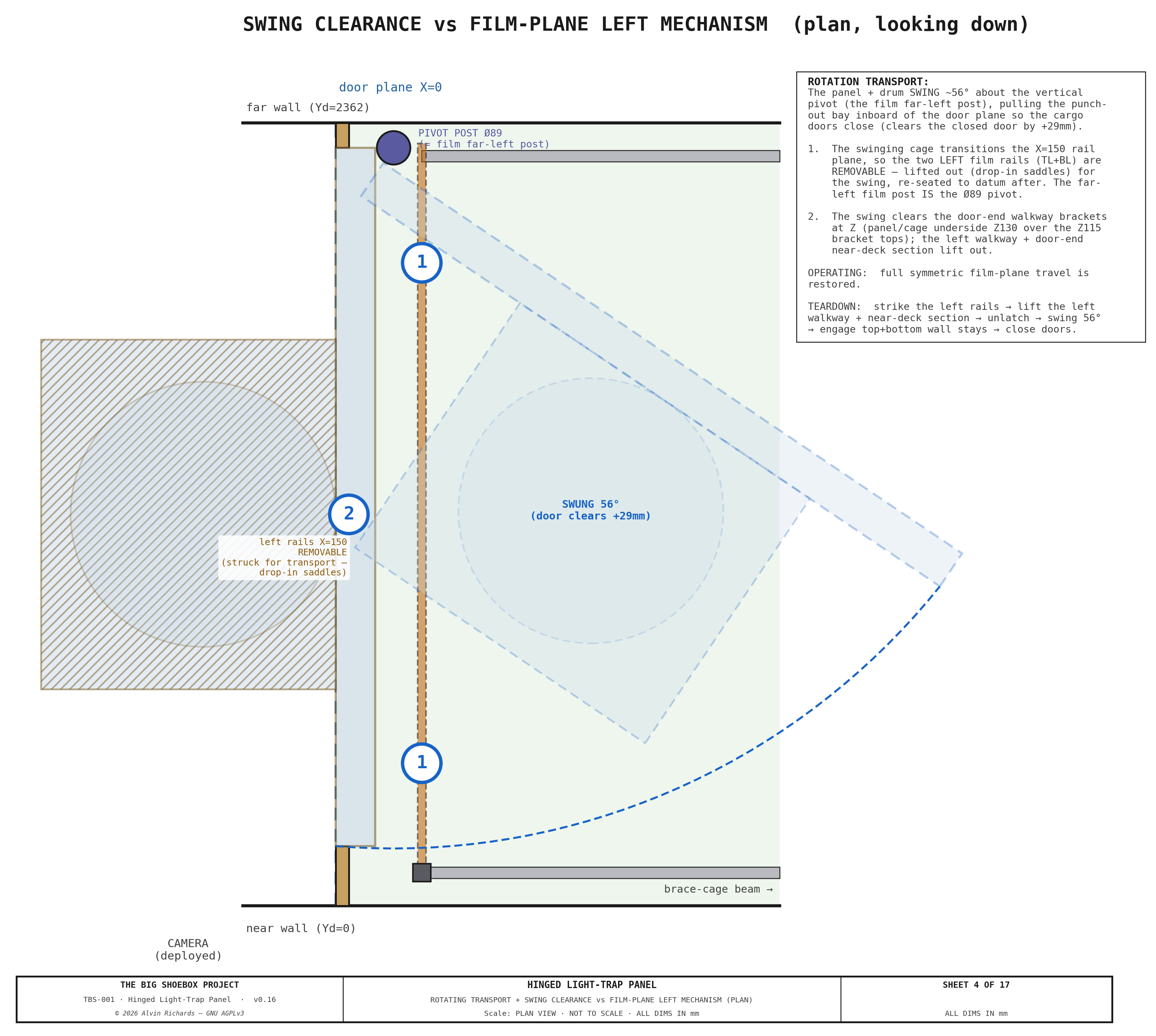
| Position | Bay front-right corner X | Container doors clear? |
|---|---|---|
| Operational (0°) | −890mm (bay protrudes ~890mm outside the door plane) | No — the cargo doors stay open during operation |
| Transport (swung 56°) | +29mm clearance to the closed-door inner face (swept-frame min X 58.6mm − 30mm door-leaf inboard) | Yes — the swept frame is fully inboard of the closed door |
5.2 Locking¶
| State | Method |
|---|---|
| Operational (0°) | 2 × interior cam latches (§4, opening edge) compress the EPDM vertical perimeter + cut seals against the door frame; the top + bottom strip-brush seals are passive (always engaged, no compression) |
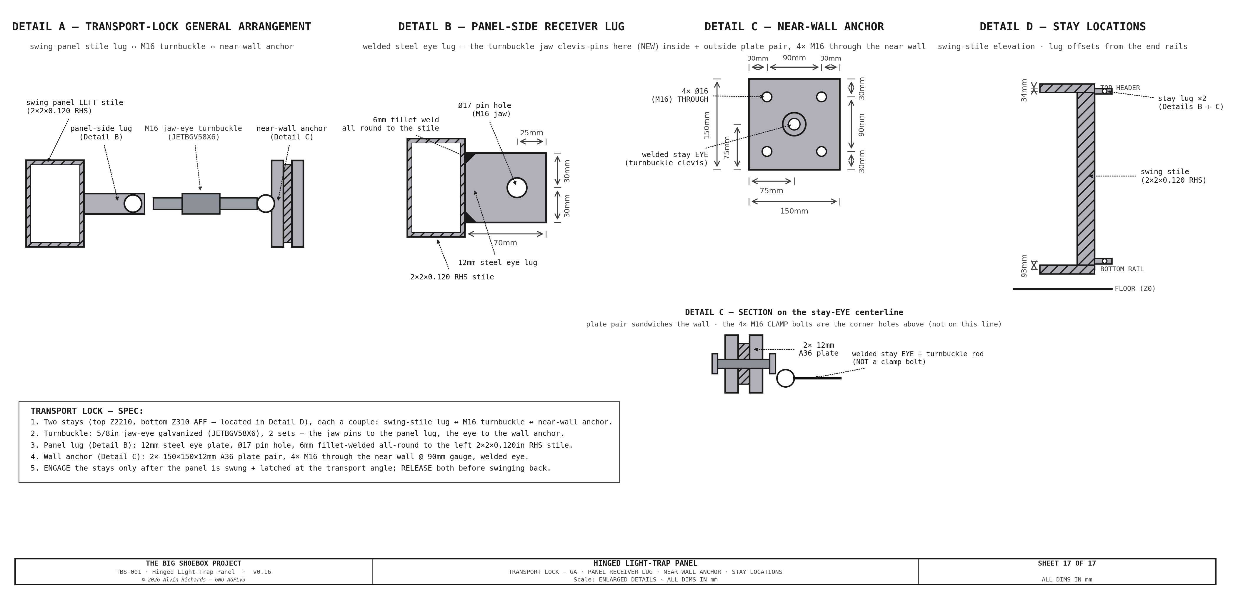
| Transport (swung 56°) | Top + bottom wall stays — hook welded to the swinging panel's left perimeter 2×2×0.120in steel SHS stile (the steel frame member at the swing cut) ↔ eye on the near wall, tensioned by turnbuckle, forming a couple. Engaged after the swing, released before swing-back. |
Stay hooks land on steel, not the skin. The transport-stay couple carries real tension, so both hooks weld to the left perimeter RHS stile of the swinging frame — not the 1/8" HDPE plastic skin. The perimeter stile is the farthest point from the pivot (best lever arm) and a continuous welded steel load path into the frame.
The complete transport lock is detailed on Sheet 17 — the general arrangement, the panel-side receiver lug (a 12mm steel eye plate with a Ø17 clevis-pin hole, 6mm fillet-welded all round to the stile — the turnbuckle jaw clevis-pins here), and the near-wall anchor (a 150 × 150 × 12mm A36 plate pair bolted through the near wall with 4 × M16 on a 90mm square — the interior + exterior backing-plate pattern of the wall-hanger / cantilever joints, since the wall can't be welded to). The turnbuckle is a 5/8in jaw-eye galvanized unit (JETBGV58X6); lug/plate/bolt sizes single-source from tbs_constants (LT_STAY_*). Both ends are modeled in 3D — the panel receiver (frame_hooks()) and the wall anchor (wall_anchors()).
Sheet 17 — Transport Lock: general arrangement + panel-side receiver lug + near-wall anchor
5.3 Floor Gap¶
The panel + drum cage ride at a 217mm floor gap, carried by the pivot post on its thrust collar + hub bearings. The gap is set by the transport-swing clearance: as the panel + drum swing across the container, the drum-cage underside must clear the tallest fixed obstacle in the swept path — the LEFT walkway's floor-leg cantilever posts, which stay bolted during the swing and stand taller than the fixed processing-tray rim. The 217mm floor gap clears the posts by 25mm (and the tray rim by 70mm; the bottom axle beam uses a shallower section to win 10mm of that from the lower hub without raising the drum), at a cost of 87mm of drum interior — still clearing a 1,780mm operator by 103mm.
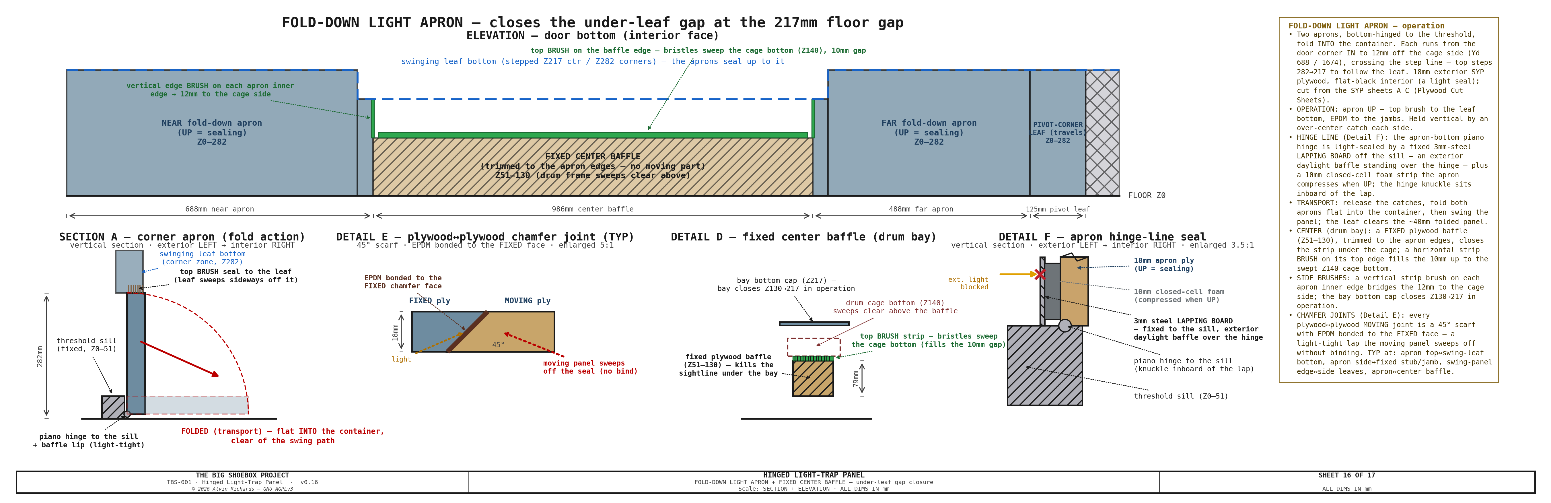
The swing is about a vertical pivot, so the cage underside stays at the same height throughout — this is what makes the deep Ø800 housing transport-feasible without a slide; a floor-mounted housing would have fouled the tray. The 217mm floor gap is closed in the operational position by the fold-down light aprons (§6, Sheet 16). The clearance is drawn on Sheet 15 (transport-swing bottom-clearance section).
Sheet 15 — Transport-Swing Bottom-Clearance Section (Yd–Z): drum-cage underside vs the fixed floor-leg posts + tray rim, walkway grate lifted out
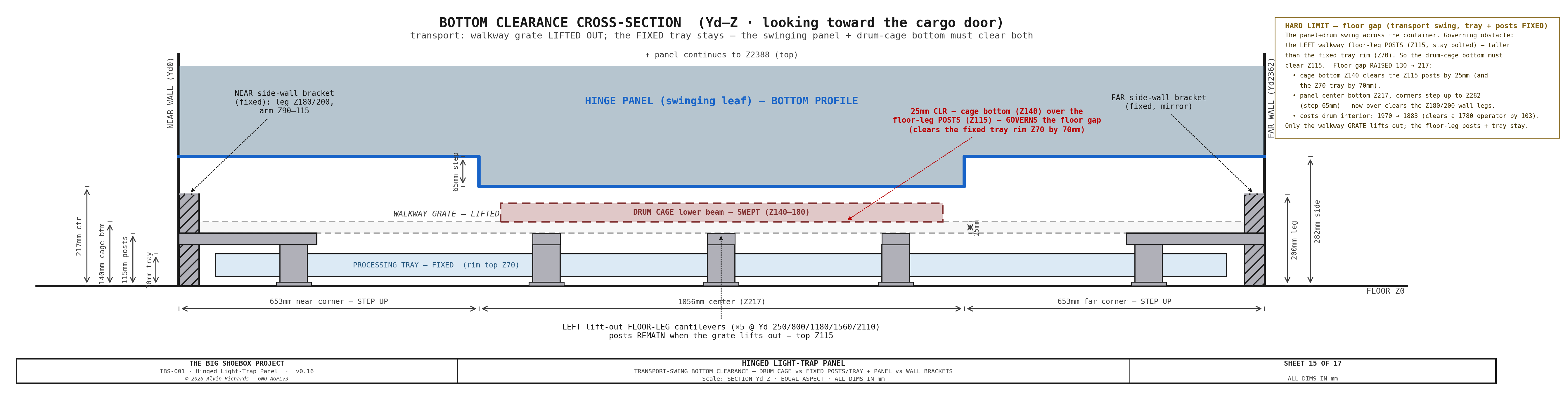
The 217mm gap would otherwise be a straight light path, so it is closed by fold-down light aprons (Sheet 16): two bottom-hinged 18mm exterior-ply flaps at the corner zones (the far one minus a 200mm fixed stub that clears the Ø220 pivot mount plate) plus a fixed center baffle under the drum bay. The apron ply cuts from the SYP sheets A–C (Plywood Cut Sheets), so it buys no sheet of its own. They stand up and seal in operation and fold flat into the container for the swing. The apron hinge line is light-sealed by a fixed 3mm-steel lapping board off the sill — an exterior daylight baffle standing over the piano hinge — plus a 10mm closed-cell foam strip the apron compresses when up, with the hinge knuckle inboard of the lap (Sheet 16 Detail F).
5.4 Transport Conversion Sequence¶
The rotation transport + swing clearance vs the film-plane left mechanism is shown in Sheet 4 (above): the panel + drum swing ~56° about the pivot, pulling the bay inboard of the door plane (clears the closed-door inner face by +29 mm); the two left film rails are struck (removable) so the swinging cage transitions the film-plane rail plane, then re-seat to the film datum.
The swing carries the drum cage through the film-plane rail line, where the film-plane mechanism's left edge sits, so the two left film rails (TL + BL) must be struck before the swing and re-seated after (the tapered dowels return the film datum). The muslin screen must be struck regardless — the fragile screen cannot travel mounted. The swing clears the door-end floor-leg posts: the cage underside passes over the post tops (they stay bolted), so no floor-leg post is demounted.
Order of operations (single person, ~10 min) — see the Operating Manual §5.5:
- Park the revolving drum and pin its rotation.
- Remove the muslin screen from its frame and stow it (rolled); knock down the demountable brace cage (saddle/thumbscrew portals).
- Lift out the left walkway + door-end near-deck section.
- Strike the two left film rails (TL + BL) — release each clamp bar, lift the rail out of its saddles, and stow.
- Release the two lift-and-turn cam latches (releases the perimeter + cut seals).
- Swing the frame ~56° inboard about the pivot, assisted (balanced about the vertical axis — no gravity torque; control momentum at the stop).
- Engage the top + bottom wall stays (the transport lock).
- Close the ISO cargo doors (they clear the swung frame by +29 mm).
Re-deployment reverses the sequence.
5.5 Pivot-Post Assembly¶
The whole movable assembly swings on a fixed Ø89×8 CHS post (3" NPS Sch-80, S355 — the reused film far-left upright, upgraded), running floor→roof and bolted at both ends to Ø220×20 mount plates: the floor plate takes the vertical + moment on a 6× M12 anchor-bolt circle into the container floor cross-member, the roof plate is bolted to the roof rail. The post is a structural positioning member carrying the ~3.6 kN·m swing cantilever (SF 3.7).
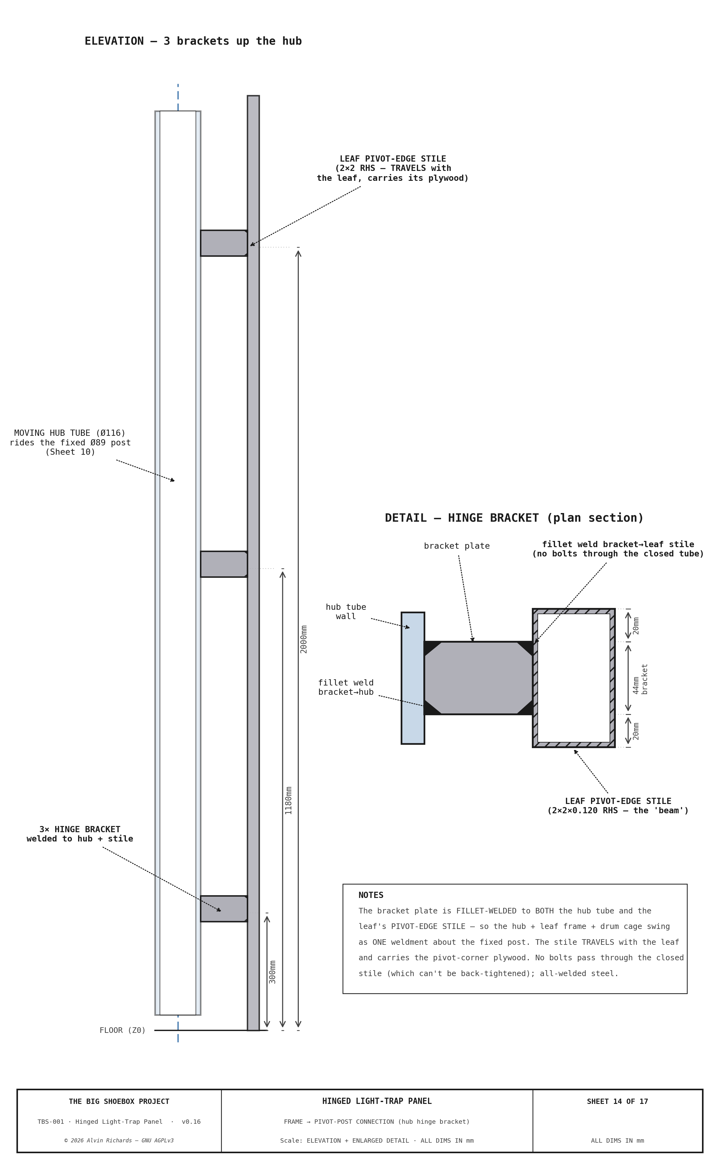
The moving hub rides the post and swings with the frame: a 51118 single-direction thrust bearing at the base carries the ~330 kg vertical load, and two iglide J journal bushings (JFM-9095-100, top + bottom) take the radial load and the overturning couple. The hub ties to the panel through three welded hinge brackets bolting to the steel center-zone jamb (2× M12 each, through the RHS into a backing plate — not the HDPE skin). The pivot post, its bearings, and the frame→hub bracket still require a structural sign-off before fab.
Sheet 10 — Pivot-Post Assembly (section + frame→hub bracket + floor anchor plate)
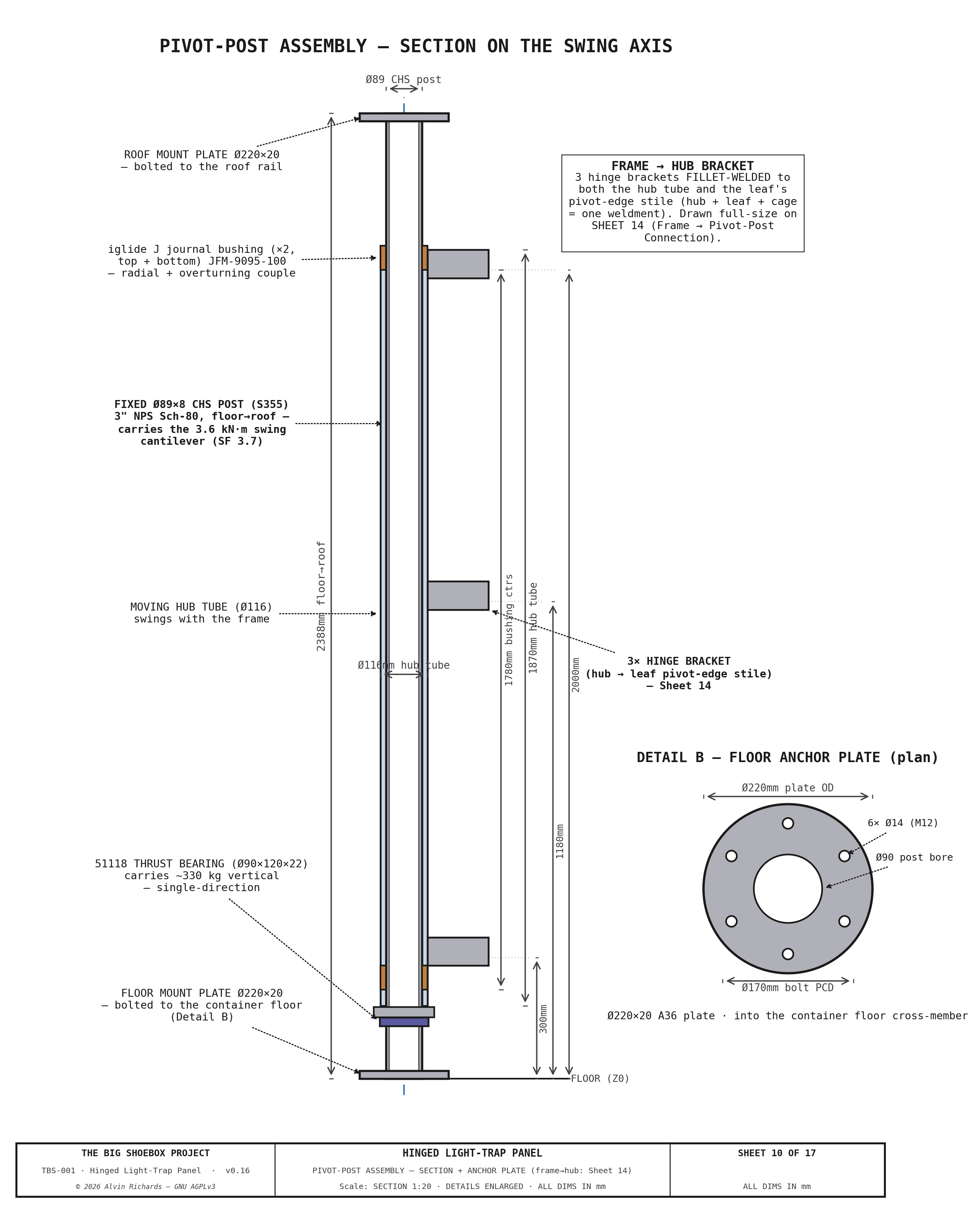
Sheet 14 — Frame → Pivot-Post Connection: the 3 welded hinge brackets tying the moving hub to the center-zone jamb
6. Light Seal Design¶
The swinging panel seals against the fixed door frame in its operational (closed) position. Five light ingress paths are sealed:
| # | Light path | Seal method |
|---|---|---|
| 1 | Panel perimeter (left/right) → door frame | 20mm EPDM gasket in an aluminum channel down each vertical edge, compressed by the 2 × McMaster 1619A74 lift-and-turn cam latches (opening edge, top + bottom) against the fixed door frame. (The top + bottom edges are strip-brush seals — paths #3/#4 — not compression EPDM.) |
| 2 | Swing cuts → fixed strips | The swinging center+corners separate from the two FIXED strips (near Yd0–180, far Yd2287–2362, which carries the pivot) along vertical cuts. A 20mm EPDM cut seal runs the full panel height down each cut, compressed by the cam latches when the panel is latched at the door plane. Replaces the old sliding-carriage beam/guide-slot brush seals. (Sheet 3, Detail D.) |
| 3 | Panel bottom → 217mm floor gap | Fold-down light aprons (Sheet 16) — two bottom-hinged 18mm exterior-ply flaps at the corner zones (the far one minus a 200mm fixed pivot stub) + a fixed center baffle under the drum bay, closing the 217mm gap under the raised leaf. Foam-strip perimeter seal, flat-black interior. Stand up + seal in operation; release + fold flat into the container for the swing. The hinge line is sealed by a fixed steel lapping board (exterior baffle over the piano hinge) + a compressed foam strip — Sheet 16 Detail F. |
| 4 | Panel top → frame gap | Fixed-frame top brush seal — the mirror of #3: a nylon-filament strip brush in a holder on the frame top rail, its bristles reaching ~30mm below the panel top edge. The drum stub shaft stops below it, so the brush runs as one continuous member across the full panel-top width — no notch — meeting across the center. The panel + drum-box top edge sweeps through the bristles as the panel swings — a deliberate ~30mm bristle overlap in the closed position, not a clash. No cam-latch compression on this edge; the bristles are the seal. (Sheet 3, Detail C.) |
| 5 | Housing surround → door frame | The Ø800 light-trap housing carries the revolving drum and swings with the panel. A second 20mm EPDM gasket rings the housing aperture (floor gap up to the housing top), concentric inboard of the panel-perimeter seal (#1), seated in the door plane. In the closed position it seals the housing surround to the frame all the way around the opening — light-tight. (3D: the door_frame() "Housing surround seal", in both the light-trap and overview models.) |
Seal verification: After mode conversion, the operator performs a 5-minute dark-adaptation check inside the container with all seals engaged. Any visible light points are marked with gaffer tape for re-sealing.
Sheet 16 — Fold-Down Light Aprons: closing the 217mm floor gap (Details A–F incl. the hinge-line lapping-board/foam seal)
7. Fixed Door Frame¶
A fixed welded door frame provides the seal landing surface (perimeter, cut, and lip seals) for the swinging panel, and the structural anchor for the wall-stay eyes.
| Parameter | Value |
|---|---|
| Material | 50 × 50 × 3mm RHS mild steel |
| Position | X=0 (container end wall inner face) |
| Function | Seal landing for the swinging-panel vertical perimeter + cut seals + housing-surround EPDM, plus the top + bottom strip-brush light seals |
| Attachment | Welded to container end wall structural members |
| Cut-seal landings | 2 × vertical EPDM landings (the swing cuts between the swinging panel and the fixed strips) |
| Bottom light seal | Fold-down light aprons — 2× bottom-hinged 18mm-ply flaps (corner zones) + fixed center baffle + 200mm pivot stub; foam-strip seal, fold flat for transport (see §6 path #3, Sheet 16) |
| Top brush seal | Mirror of the bottom: continuous nylon-filament strip brush in a holder on the frame top rail, bristles reaching ~30mm below the panel top edge, full panel-top width and continuous across the center (the drum does not reach the top, so no notch) — the panel + drum-box top edge sweeps through the bristles (see §6 path #4) |
8. Parts List¶
8.1 Panel Structure¶
| Item | Spec | Qty | Supplier | Est. cost |
|---|---|---|---|---|
| 2×2×0.120in steel SHS (6 m bulk lengths) | Frame perimeter + internal members | 4 ea | Metal Supermarkets | $120–$160 |
| 1/8" black HDPE sheet (48×96) (46684) | Panel skins, both faces (~12 m², 4× 4×8 ft sheets). 1/8" HDPE is nearest stock to the 4mm PANEL_SKIN_T nominal (weld-compatible with the HDPE housing/drum); the U-channel grid (~400–450mm centers) keeps the skin flat, so the 0.8mm is immaterial. US Plastics 46684 $123.34/sheet. | 4 sheet | US Plastics / TAP Plastics | $493 |
| Fan B near-corner ply (swinging mount panel + fixed side part + cooler base, 23/32" exterior SYP, from the sheets A–C offcut) (303564747) | 23/32" (18mm) RTD Southern Yellow Pine exterior sheathing. The Fan B near corner is THREE ply pieces: the SWINGING fan-mount panel (473×943, Yd180→653, carries the Ø150 fan CENTERED, travels with the hinge leaf), the FIXED side part (180×943, Yd0→180, stays on the pinhole side), and the fold-down apron (billed separately as panel-bottom-apron). Those two upright pieces PLUS the cooler stowage base plate (600×350) all NEST INTO THE SYP OFFCUT (Plywood Cut Sheets, sheets A–C), so no separate sheet is bought (was a dedicated ¾" PT sheet, retired 2026-09-30). STANDARD exterior per the project rule — PT was over-spec for a dry, vented mount. Seal cut edges. | 1 cut from the SYP sheets A–C | shared (Plywood Cut Sheets) | $0 |
| 1"×1"×1/8" Al angle, 8 ft — corner-zone stiffener grid (2EYP1) | Corner-zone anti-oil-can rib grid — light-tightness is carried by the two black HDPE skins and the latch/fan load by the RHS frame + ply band, so the corner only needs stiffening against oil-can. Per corner: 1 vertical (2,258mm) + 2 horizontal (653mm) 1"×1"×1/8" (25×25×3.2mm) Al angle ribs, ~325×750mm bays, holding both 1/8" HDPE skins flat within the 40mm framed cavity. The leaf is VERTICAL, so skin self-weight is in-plane; the grid only resists out-of-plane oil-can (works with the U-channel skin retainers at ~400-450mm centers, report §2.5). ~7.1m installed → 4× 8 ft (2,438mm) sticks for clean piece-fit (2 sticks → the 2 verticals, 2 → the 4 horizontals + spare). ~2.9 kg installed. Grainger 2EYP1 $12.20/8ft firm (2026-07-29). | 4 ea | Grainger | $49 |
| 20mm EPDM gasket (per meter, closed-cell) (B089GJQ96Z) | Perimeter seal (~10 m) + housing-surround ring (~6 m) + 2× vertical cut seals at Yd180/2287 (~5 m) | 21 m | Amazon (OKAYASU) | $24–$52 |
| Aluminum U-channel, 1/8-panel (per meter) | Gasket retainer + 1/8" HDPE-skin retention (perimeter + housing-surround + stiffener grid). SECTION: aluminum '1/8-panel' U-channel — inner slot ~3.2mm (captures the 3.18mm/PANEL_SKIN_T HDPE skin), ~10–12mm legs, ~1.5mm wall. TOTAL LENGTH: 40m (pick a stock 1/8-panel profile; only the 3.18mm slot is fixed by the skin). | 40 m | Online Metals | $120–$200 |
| Lift-and-turn tight-hold cam latch (McMaster 1619A74) (1619A74) | TWO interior-mounted latches on the OPENING (free) edge of the swinging panel — top + bottom — clamping it to the fixed door frame (the pivot edge is hinged; a frame stop takes the outward direction, so only the free edge needs latching). Turns from the INTERIOR face; the reversible-offset cam hooks a welded steel keeper on the stub-wall steel frame outside, drawing the panel onto the 20mm EPDM seal (panel opens INWARD only). 150 lbf max clamp; ADJUSTABLE latching distance 1-3/4 to 2-1/8in (44-54mm); 1/4in max panel thk; 11/16in through-hole; black-painted zinc; mounting fasteners incl. Lift-and-turn = vibration-resistant for transport + hand-releasable from inside for egress. Mounts through the panel-frame RHS; the latch nut is tightened via a coaxial over-bore in the far tube wall + box spanner, then a light-tight plug (or a welded tapped boss — fab detail on Sheet 12). $30.57 ea firm. | 2 ea | McMaster-Carr | $61 |
| 1/8" black HDPE sheet (48×96, ×2) (46684) | B2 punch-out bay — 4-wall light-tight tube (~890mm deep) around the housing; 4 walls, 2 per 4×8 sheet. 1/8" HDPE nearest stock to 4mm (weld-compatible with the HDPE housing/drum); EPDM lip cut from the panel-epdm perimeter roll (not billed here). US Plastics 46684 $123.34/sheet. | 2 sheet | US Plastics / TAP Plastics | $247 |
| 1/8" 18-8 SS blind rivets — HDPE surround → frame lap (100-pack ×2) (97525A435) | Fasten the HDPE surround (B2 bay walls + upper/lower floor caps + center-zone face skins) to the steel center-zone frame at the panel-plane lap — ~140 rivets over the lap edges (2 jamb lines ~35 each + cap/skin laps) → 2× 100-pack. 1/8" (Ø3.18) 18-8 SS blind rivet, grip 0.313–0.375", drill #30 (Ø3.3), set with a DP8010 sealant bead for light-tightness (same rivet family as the light-trap housing→frame lap, ll-rivets-housing). Hingepanel Sheet 7. $14.59/100. | 2 pack | McMaster-Carr | $29 |
| Flat black paint (RAL 9005) | Bay/weld touch-in (HDPE skins are pre-pigmented black) | 1 qt | Local fab | $10–$20 |
| Fold-down light aprons + fixed baffle/pivot stub (18mm ext ply, from the SYP sheets A–C offcut) + piano hinges + foam seal + hold-up catches | Closes the 217mm under-leaf floor gap opened by the drum-cage clearance (hingepanel Sheet 16). Two bottom-hinged fold-down aprons (near corner Yd0–653 + far corner Yd1709–2162; the far one minus a 200mm FIXED stub Yd2162–2362 that clears the Ø220 pivot mount plate) + a fixed center baffle under the drum bay. 18mm exterior SYP plywood, flat-black interior — the ~0.5 m² of ply NESTS INTO THE SYP OFFCUT (Plywood Cut Sheets, sheets A–C: corridor + pinhole panels), so no separate apron sheet is bought (was a dedicated 12mm sheet); this lot is the piano hinges + foam + catches. 2× continuous (piano) hinges to the threshold, closed-cell foam-strip perimeter seal, 2× over-center hold-up catches; folds flat into the container for the transport swing. HINGE-LINE seal (Sheet 16 Detail F): a fixed 3mm-steel lapping board off the sill — an exterior daylight baffle standing over the piano hinge — + a 10mm closed-cell foam strip the apron compresses when UP (knuckle inboard of the lap). Est.; lapping-board steel is an offcut, foam within the seal roll. | 1 lot | Home Depot / McMaster | $85–$140 |
| 12" round pull handle — McMaster 1871A65 (same as the drum handle) + 1/4" screws into rivnuts, matte-black (1871A65) | Interior panel-swing pull handle (§4.3) — the SAME off-the-shelf part as the interior drum handle (ll-grab-rail): Ø12.7 bar, 12.13" grip, 2.06" standoff. Screws into 1/4"-20 rivet-nuts set in the panel-frame RHS near wall — the swing load reacts into the STEEL frame, not the HDPE skin (rivnuts because the 3mm tube wall can't be tapped, and there is no back-access to a nut). Matte-black powder-coat (optically dead). $6.43 firm. | 1 ea | McMaster-Carr | $6 |
| Panel total | $1,244–$1,457 |
The panel pivot post + bearings + drum cage + wall stays are itemized in §8.3.
8.2 Housed Revolving Door (housing + drum)¶
| Item | Spec | Qty | Supplier | Est. cost |
|---|---|---|---|---|
| 3/16" UV-stab HDPE sheet, black — 48×96 (×3) (46685) | Ø800 fixed housing shell (~56 ft², ~2,062mm tall — spans beam-to-beam), rolled + extrusion-welded from 3× 4×8 ft 3/16" (≈5mm) UV-stab HDPE sheets — the 99" circumference needs 3× 48" sheet widths (2 fall ~15" short). ~33% offcut on the 3rd sheet; a 5×10 ft sheet would cut to 2 (optimize at order). US Plastics 46685 $184.99/sheet. | 3 sheet | US Plastics / TAP Plastics | $555 |
| 1/8" black HDPE sheet — 48×96 (×3) (46684) | Ø764 revolving drum shell (~49 ft², ~1,890mm tall) — rolled + extrusion-welded 1/8" HDPE (94.5" circ needs 3× 48" widths). A light-tight cover over the steel/Al structure; its 1/8" is non-structural (lighter = easier revolve, less bearing load). The 2 end caps are now 8mm 6061-T6 ALUMINUM (ll-caps-al) — NOT HDPE — since they carry the stub-shaft hubs into the SKF 6215 bearings. US Plastics 46684 $123.34/sheet. | 3 sheet | US Plastics / TAP Plastics | $370 |
| 8mm 6061-T6 aluminum plate — 2 drum caps (Ø755) | Both drum end caps (8mm 6061-T6, Ø755, identical) — waterjet 2 discs + the 4×M10 hub bolt circle (Ø120 PCD) + the 280° rim-angle rivet holes. STRUCTURAL: carry the bolted stub-shaft flanges into the SKF 6215 bearings. Est. material + waterjet (Online Metals); firm at order. | 1 lot | Online Metals / Industrial Metal Supply | $400–$700 |
| 25×25×3 6061-T6 Al angle — 2 rim rings (rolled R427) | 2 rolled rim-angle rings (25×25×3 6061-T6, R427, ~5.4 m total) — the shell→cap lap-joint standing lip, riveted to both Al caps over the 280° arc. Material + roll. Est.; firm at order. | 1 lot | Online Metals / Industrial Metal Supply | $45–$90 |
| Bearing retaining rings + upper end-retainer plate (90154A895) | Axial retention for the 2× SKF 6215. INNER race — EXTERNAL retaining rings on the Ø75 stub shafts (McMaster 90154A895, for OD 75mm, $7.05/pack — shaft groove Ø72.0 × 2.65mm, ring 2.5mm): 3 total = 2 on the LOWER shaft (both sides, floating bearing captive) + 1 drum-side on the UPPER shaft. The UPPER shaft's beam-side clip is REPLACED by an END-RETAINER PLATE (Ø90 × 4mm mild-steel disc, ≈$3 blank, central Ø10.5 c'bore) bolted by 1× M10×25 flat-head CSK screw (from the F1 CSK pack) into a tapped hole in the shaft end — its rim clamps the inner-race face so the drum's hanging load runs through a bolted member, not a lone circlip (transport-shock robust). OUTER race — 1× INTERNAL retaining ring in the Ø130 upper-ring bore (LOCATED upper bearing, beam side; McMaster 98455A170, for ID 130mm, $7.26/pack — bore groove Ø134.0 × 4.15mm, ring 4.0mm). The LOWER bearing FLOATS (plain Ø130 H7 bore, no ring). ≈$17 firm. | 1 lot | McMaster-Carr | $17–$18 |
| SKF 6215-2RS1 sealed bearing (6215-2RS) | Top and bottom (drum rotation). Ø75 bore × Ø130 OD × 25mm wide, C=52.7 kN, both-sides sealed (6215-2RS / 6215-2NSE; SKF designation 6215-2RS1). Buy the ABEC-1 grade: the drum is a hand-rotated, low-speed, low-load light-lock — the tighter ABEC-3 tolerance buys nothing here (SKF's standard 6215-2RS1 is Normal/P0 = ABEC 1). VERIFIED $60.59 ea at Bearings Direct 2026-07-18. ALT: McMaster 6138K125 @ $394.88 ea — a heavy commodity-bearing premium, prefer the distributor. | 2 ea | Bearings Direct / McMaster-Carr | $121 |
| 75mm Ø × 150mm steel stub shaft | Bearing shafts | 2 ea | Steel service center | $30–$50 |
| 1/8" 18-8 SS blind rivets — shell→cap lap (100-pack) (97525A425) | Shell→cap lap rivets (~35/cap ×2 ≈ 70 → 1 pack of 100). 1/8" (Ø3.18) 18-8 SS low-profile head, grip 0.188–0.25", drill #30 (Ø3.3). Wet in DP8010 for light-tightness. $13.83/100 firm. | 1 pack-100 | McMaster-Carr | $14 |
| 1/8" 18-8 SS blind rivets — housing→frame lap (100-pack) (97525A435) | Housing→frame lap rivets (~26/edge ×2 ≈ 52 → 1 pack of 100). 1/8" (Ø3.18) 18-8 SS, grip 0.313–0.375", drill #30. $14.59/100. | 1 pack-100 | McMaster-Carr | $15 |
| 3M Scotch-Weld DP8010 structural adhesive (green, 45 mL) (7467A36) | Structural LSE acrylic — bonds + light-seals the HDPE lap joints (shell→cap, housing→frame) and wets the open rivet mandrel bore for light-tightness. (The opening-edge channels are rivet-only as of 2026-09-08 — no DP8010.) 45 mL cartridge + mixing nozzle. $76.29 firm. | 1 ea | McMaster-Carr / 3M | $76 |
| Eagle Al H-divider — opening-edge H-mullions (×4) (SGN-113) | 4× Al H-mullion (Eagle Aluminum SGN-113 'H-divider 1-3/8" for 3/16" material', mill finish, 12 ft) — one at each of the 4 housing opening edges. The housing is built as TWO arc panels that SLIDE into the H slots (no welded seam): one slot takes the arc-panel edge (full height), the other the sill/header band edge (top+bottom). Riveted thru the flange + HDPE @120mm (Ø3.18 SS blind); mullion ends bolt via L-clip to the 4 support strips (ll-channel-strip; L-clips + M8 in the fasteners lot). One 12 ft stick per mullion (~82" each). $38/12 ft. Confirm the alloy (likely 6063) + slot/leg depth on order. | 4 12ft | Eagle Aluminum / Orange Aluminum | $152 |
| 6063-T5 Al U-channel — rotating-drum opening-edge stiffeners (×2) + rivets | 2× RIVETED Al U-channel (~10×15×2, ~2.1 m each ≈ 4.2 m) capping the ROTATING DRUM's two free HDPE opening-jamb edges (mirrors the housing opening channels but for the 3.18mm shell — rivet-only, no bond; legs lie flat so ~2mm radial proud clears the 13mm drum↔housing gap). Ø3.18 18-8 SS blind rivets @120mm thru both legs + shell (from the SS blind-rivet packs). Est.; confirm stocked section (2026-09-08). | 1 lot | Online Metals / McMaster-Carr | $30–$55 |
| 1×1×1/8in 6061-T6 Al angle — channel-support beams (×4) + rivets | 4× 1"×1"×1/8" (25×25×3.2) 6061-T6 aluminum equal-leg angle, ~1.2 m (4 ft) each (one strip per 4 ft piece) — one across each housing opening (top + bottom), spanning the full cage width (~962mm, rail-to-rail) so the ends land on the X-near/far frame rails, NOT floating. They give the two housing opening-edge U-channels (ll-edge-channel) a member to bolt to (1× M8/end via L-clip on the up-leg) at top and bottom, and are themselves Ø3.18 18-8 SS blind-riveted to the frame beams (flat leg on the beam; from the SS blind-rivet packs). Metals Depot 1×1×1/8 Al angle $17.20/4ft. | 4 4ft | Metals Depot / Online Metals | $69 |
| #4 (3/16") black-nylon strip brush — running-gap light-seal wiper (×4 lines) | 4 vertical #4 (3/16") staple-set strip brushes — the running-gap light seal (drum↔housing). Metal channel backing, 0.008" BLACK nylon, 0.687" (17.5mm) trim; each snaps into an Al flange holder (ll-wiper-holder) that is flange-riveted to the rotating drum OD (rivets in the flange, clear of the brush — a 3/16" channel is too small to rivet through). One 8 ft (2.44 m ≥ 1.97 m drum ht) piece per line → 4× 8ft. Est.; firm at order. | 4 8ft | Gordon Brush / Tanis Brush | $88–$160 |
| Anodized-Al straight-flange holder for the #4 wiper brush (×4 lines) (AH400436) | 4× extruded anodized-aluminum straight-flange holders (0.050" wall) for the #4 (3/16") strip brush — the brush channel snaps in; the offset flat flange is DP8010-BONDED (primary — spreads the load over the whole flange so nothing pulls through the soft HDPE) + blind-riveted (with backup washers inside) to the drum OD, so fasteners land in the aluminum flange, clear of the brush. One 8 ft length per line → 4× 8ft. Exact profile P/N confirmed at order (Tanis/Gordon release the section via CAD/quote). | 4 8ft | Tanis Brush / Gordon Brush | $72–$160 |
| 12mm closed-cell neoprene — top/bottom cap wiper seals | Top + bottom drum-cap wiper seals (12mm closed-cell neoprene, PSA back) + silicone bead to the frame plates. The drum↔housing running-gap seal is now the drum-mounted brush (ll-wiper-brush), not felt. | 1 lot | Canal Rubber / McMaster-Carr | $25–$40 |
| Silicone bead sealant (black, UV-stable) (RDX1001bl) | Bearing-housing / light-trap seam seal. Maxisil black natural-stone silicone, 10.5 oz (weather/UV grade, neutral-cure — not a mildewcide bath caulk). | 1 ea | Home Depot | $20 |
| 12" round pull handle — McMaster 1871A65 (1871A65) | Interior handle — off-the-shelf 12.13" unthreaded-through-hole-mount round pull handle (Ø0.5" bar, 2.06" standoff, 1/4" mounting screws). BOLTED at its two feet to the handle stile (ll-handle-stile) — 1/4" screws into 1/4"-20 rivet-nuts set in the hollow 5mm RHS wall (a blind insert gives full thread engagement + can't strip the thin wall) — NOT welded, and not to the drum wall. $6.43 firm. | 1 ea | McMaster-Carr | $6 |
| 40×40×5 SS RHS pull-handle stile (cap→cap) + M12 cap bolts | Steel stile (40×40×5 SS RHS, ~2.1 m) spanning + bolted between the two Al caps — carries the pull-handle load into the structural caps, NOT the thin HDPE wall. The open RHS is closed at each end by a SOLID TAPPED STEEL PLUG (2× ~30×30×40 blocks cut from bar, locked in the tube by 2× M8 cup-point grub/set screws each — anti-rotation); an M10 countersunk bolt driven from the cap's OUTSIDE face, through the cap into the tapped plug (sealed DP8010), secures each end — wrench-accessible, unlike a bolt buried in the tube. The off-the-shelf pull handle (ll-grab-rail, McMaster 1871A65) bolts to the stile (1/4" screws into 1/4"-20 rivet-nuts set in the hollow RHS wall). Est.; firm at order. | 1 lot | Metal Supermarkets / Online Metals | $50–$95 |
| Matte-black interior finish | Black-pigmented sheet (no etch-prime); scuff + flat-black touch-in at welds | 1 ea | Local fab | $40–$70 |
| Bolts/nuts/isolation washers — cap/ring/collar/stile/handle/edge/housing (91294A328) | 18-8 SS, buy one pack per line (generous spares): F1 cap→flange 8× M10×1.5 CSK into the TAPPED steel flange — Ø11 clearance in the cap only, no nut (the flange is a machined part, so it is tapped directly on the Ø120 PCD; 91294A328 $11.58/25); F2/F3 ring/collar→MOUNT PLATE 14× M10×1.5 COUNTERSUNK flat-head TAPPED into the Ø240×12 steel mount plates — flush in the ring/collar underside (McMaster 91294A334, $5.22/10 → 2 packs $10.44; same CSK family as F1); F4 stile→cap 2× M10×1.5 CSK driven from the cap outside face THROUGH the cap into the TAPPED RHS-end plugs (from the F1 CSK pack) + 4× M8 cup-point GRUB/SET screws locking the plugs (anti-rotation — ~$8/pack, SKU to source); F5 pull-handle feet 4× 1/4"-20 screws into 1/4"-20 steel RIVET-NUTS (blind inserts set in the hollow 5mm RHS wall — full thread engagement, can't strip the thin wall; the 4 inserts hand-set with a draw bolt, no dedicated tool — ~$8/pack; screws 90272A537 $7.21/100); F6 edge-channel→beam 8× M8×1.25 (91280A083, $11.17/50); F7 housing→panel 8× M10×1.5 CSK (91280A370, $10.55/25) + 8× M10 nuts (90576A118, $9.53/50); W ~22× M10 nylon isolation shoulder washers (95610A400, $18.39/100) at every steel↔Al/HDPE joint. Blind rivets + the bearing mount plates are separate lines (the ring/collar rivet-nuts are GONE — they tap the 12mm plate directly). ≈$95 (F4 grub-screw SKU pending). | 1 lot | McMaster-Carr | $95 |
| Bearing mount plates — 2× Ø240×12 steel disc | Ø240 × 12mm A36 steel disc, one per hub — welded (fillet, both sides) across each 50×50 axle beam; the SKF 6215 ring/collar bolt (M10 tapped) into it, since the ring's Ø200 bolt circle is far wider than the 50mm beam (only 2 of 6 bolts would land on the beam). Waterjet/laser the disc + the Ø80 center clearance bore + the 6/8× M10 tap-drill holes on the Ø200 PCD; tap M10. ~3.4 kg ea. Est. material + cut (Online Metals plate + SendCutSend), firm at order. | 2 ea | Online Metals / SendCutSend | $24–$44 |
| 1/8" blind rivets + backup washers — brush-holder flange → drum OD (97447A015) | ~72 rivets (4 brush-holder lines × ~18 @ 120mm) fastening the Al holder flanges to the rotating drum OD — grip ~4.5mm (1.27mm Al flange + 1/8" HDPE). Blind rivets (97447A015, $10.78/250) with Ø1/8" BACKUP WASHERS on the blind (inside) face (~$5/pack) so the bulb can't pull through the soft HDPE. The rivets are the mechanical backup — the flange is PRIMARY-BONDED to the shell with DP8010 (existing ll-dp8010 adhesive), which spreads the load over the whole flange. ≈$16 firm. | 1 lot | McMaster-Carr | $16 |
| 1/8" 18-8 SS blind rivets — housing skin → outer beam face (100-pack) (97525A425) | ~24× 1/8" (Ø3.18) 18-8 SS blind rivets fastening the housing skin's top + bottom edges DIRECTLY to the steel frame top + bottom beams (2× 100° arcs each, ~150mm pitch). The skin now extends to the OUTER beam face and fixes straight to the beam — the rolled rim-angle is dropped (2026-09-08). A blind rivet suits the CLOSED 3mm RHS beam: the set head forms inside the bore (no internal access) and bears on the full wall, vs only ~2 threads for a self-driller; 18-8 SS bites the 3mm steel far better than an aluminum rivet. Grip 0.188–0.25" (4.8–6.35mm) fits the 5mm HDPE skin + 3mm steel wall; drill #30 (Ø3.3). Same SS rivet as the shell→cap lap (97525A425). $13.83/100 firm. | 1 pack-100 | McMaster-Carr | $14 |
| Fabrication — roll + weld 2 HDPE cylinders, roll rim-angle, fit metal caps/bearings | ~16–22 hrs: roll + hot-air/extrusion-weld the 2 HDPE cylinders, roll the Al rim-angle rings, fit the metal caps + SKF 6215 bearings + stub shafts, rivet the lap joints, rivet the 4 channel-support strips to the frame beams, mount the drum brush holders + edge channels + pull-handle stile. | 1 lot | Local plastic + metal fab | $800–$1,150 |
| Lightlock total | $3,144–$4,155 |
8.3 Swing Pivot Hardware¶
| Item | Spec | Qty | Supplier | Est. cost |
|---|---|---|---|---|
| Ø89×8mm CHS pivot post + machined hub / thrust collar | Upgrades the reused film far-left upright; carries the ~3.6 kN·m swing cantilever — SF 3.7 in S355. PIPE sourced: 3" NPS Sch 80 (Ø88.9 OD × 7.6mm wall), 36" ≈ $135 (Speedy Metals). The machined hub / thrust collar + 2 journal bands (Ra ~0.4 µm, iglide runs on soft shafts) are FAB → pending blueprints. Band held est pending the fab quote. | 1 ea | Metal Supermarkets / Speedy Metals | $180–$300 |
| Thrust ball bearing, 51118 (Ø90 bore, single-direction) (51118) | Carries the ~330 kg (3.24 kN) vertical load at the post base; thrust-only (radial + moment taken by the iglide sleeves). 51118 = 90 × 120 × 22mm, static Cₒ ≈190 kN → SF >50; single-direction (gravity-down). Ø90 bore matches the Ø89 post — the machined thrust collar bears on the shaft washer. Commodity part: generic ~$25–40, branded FAG/SKF ~$50–85 (do NOT buy at Motion/Applied industrial list ~$430). Chrome steel: grease + wipe annually (humid darkroom); stainless S51118 available ~$100+ if preferred. | 1 ea | Bearings Direct / Amazon / VXB | $80 |
| iglide J flange bushing, Ø90 bore (JFM-9095-100) (JFM-9095-100) | Top + bottom radial location of the post. igus iglide J self-lubricating polymer, Ø90 ID × Ø95 OD × Ø103 flange × 100 mm long. The FLANGE gives axial location against the hub face; the OD is a light press into the hub bore. Axial load is on the 51118 thrust bearing. Maintenance-free, no oil; inert plastic — chemical-resistant (iglide J passed the igus chemical filter; iglide X isn't offered at Ø90). Service pressure ≈1.3 N/mm² vs ≈35 N/mm² allowable (>25× margin); runs on the unhardened S355 post. $130.53/ea, ships in days. | 2 ea | igus | $261 |
| Pivot floor/roof mount plates + anchor bolts + 3 hinge brackets | Floor + roof Ø220×20 A36 steel mount plates (waterjet: Ø90 post bore + 6× M12 clearance on Ø170 PCD each) bolting the fixed Ø89 post to the container floor cross-member + roof rail; 12× M12 anchor bolts; 3× welded hinge brackets tying the moving hub to the steel center-zone jamb (2× M12 each, through the RHS into a backing plate — not the HDPE skin). Est. material + waterjet + fab; firm at the fab quote (the pivot needs a structural sign-off). Hingepanel Sheet 10. | 1 lot | Local fab / McMaster-Carr | $70–$120 |
| Drum support cage, 2×2×0.120in steel SHS | Steel welded box cage carrying the Ø800 housing + drum on the swinging leaf — 4 corner posts + perimeter rails + a top & bottom axle beam at the drum axis, ALL 50×50×3 RHS (2×2×0.120in stock, the axle beams = the perimeter section: the 962mm span is barely stressed, δ≈0.3mm). The 2× Ø240×12 bearing mount plates (ll-mount-plates) are fillet-welded across the beams (steel↔steel) — the SKF 6215 ring/collar tap into them. Material inside the local-fab lot, so no separate per-ft line. | 1 lot | Local fab | $70–$120 |
| Top + bottom wall stays + 4-bolt anchor plates (JETBGV58X6) | Transport lock — 2× M16 jaw-eye turnbuckle + 2 panel-side welded eye lugs (12mm steel, Ø17 clevis-pin hole, fillet-welded to the stile) + inside/outside wall anchor plates (150×150×12 A36 pair, 4× M16 through-bolts per anchor @ 90mm square); hingepanel Sheet 17 | 2 set | Fasteners Plus | $90–$120 |
| Drop-in rail saddles + tapered dowels | For the 2 removable left film rails (TL + BL); dowels set the film datum | 4 ea | Local fab / McMaster-Carr | $80–$130 |
| Swing total | $831–$1,131 |
8.4 Fixed Door Frame¶
| Item | Spec | Qty | Supplier | Est. cost |
|---|---|---|---|---|
| 50×20×3 RHS (6 m bulk lengths) | Frame members — 50×20×3 RHS (50mm FACE = the seal landing, 20mm depth). REUSES the IBC retaining-bar section (ibcf-rhs, 50×20×3) so it needs no bespoke order. Non-weight-bearing (the pivot post carries the hinge panel) — the frame only takes seal-compression + cam-latch load. | 3 ea | Metal Supermarkets | $90–$120 |
| Tight-seal nylon strip brush + aluminum holder (~4.7 m, top + bottom) (74405T12) | Top + bottom door-frame light seals (paths #3–#4) — 2× McMaster 74405T12 nylon Tight-Seal Strip Brush (8 ft, 1" overall height, $28.88 ea) in 2× McMaster 8813T53 aluminum holder channel (8 ft, $35.37 ea) = $128.50 firm; covers full panel width top + bottom (~2× C_WID ≈ 4.7 m ≈ 15.5 ft, from 4× 8 ft lengths). The swinging panel edge SWEEPS THROUGH the bristles, so a brush (not a compression EPDM, which would drag under the sideways sweep) — same principle as the drum-opening brush seals. | 1 lot | McMaster-Carr | $129 |
| Welding / fabrication | Frame assembly + BOLTED wall attachment (M10 @ ~300mm through the frame into the container's steel cargo-door opening — reversible, no hot work on the container) + the welded opening-edge U-channel (Yd0–180) that carries the 2 cam-latch strike plates and welds to the door-frame left stile. | 1 lot | Local fab | $200–$350 |
| Door total | $419–$599 |
8.5 Cost Summary¶
| Assembly | Low estimate | High estimate |
|---|---|---|
| Panel structure (incl. B2 bay + pull handle) | $1,244 | $1,457 |
| Housing + drum (plastic skin) | $3,144 | $4,155 |
| Swing pivot hardware | $831 | $1,131 |
| Fixed door frame | $419 | $599 |
| Total | $5,638 | $7,342 |
9. Maintenance¶
| Interval | Task |
|---|---|
| Every use | Dark-adaptation light seal check (5 min) — mark any light points with gaffer tape |
| Every 20 mode conversions | Inspect the EPDM cut seals at the swing boundaries (Yd180/2287) for wear |
| Every 6 months | Inspect EPDM perimeter gasket compression; replace if permanently deformed |
| Every 6 months | Inspect neoprene drum seals (top/bottom) for wear and adhesion |
| Annually | Inspect the wall-stay turnbuckles, hooks, and eye anchors; verify tension at the locked angle |
| Annually | Grease the 51118 pivot thrust bearing; the iglide journal bushings run dry — do not oil/grease them — wipe the post journal bands clean and check for free, smooth rotation |
| Annually | Check SKF 6215 bearings for roughness — sealed for life, replace only if failed |
| Annually | Check the drop-in rail saddles + tapered dowels seat the left film rails square to datum |
| Annually | Inspect the cam latches for clamp force; adjust the latching distance or replace the keeper |
| Every 2 years | Re-seal drum top/bottom neoprene wiper strips and silicone bead |
| As needed | Re-apply flat black interior paint where scuffed or worn |
10. Source References¶
| Item | Source |
|---|---|
| SKF 6215-2RS1 bearing specification | SKF Product Catalog — radial load 52.7 kN basic dynamic (C), sealed, C3 clearance |
| Lift-and-turn cam latch | McMaster 1619A74 — adjustable lift-and-turn tight-hold cam latch, 150 lbf |
| Turnbuckle + eye/hook (wall stays) | McMaster-Carr turnbuckles — drop-forged jaw/eye turnbuckles for the transport lock |
| Pivot thrust bearing (51118) | Motion — SKF 51118 — single-direction thrust ball bearing, Ø90 × 120 × 22mm, static Cₒ ≈190 kN, for the pivot base |
| Pivot journal bushings (JFM-9095-100) | igus — iglide J JFM-9095-100 — iglide J self-lubricating flange bushing, Ø90 ID × 95 OD × Ø103 flange × 100L, top + bottom post radial location |
| EPDM gasket material | McMaster-Carr — closed-cell EPDM, UV-stable |
| Neoprene wiper strip | McMaster-Carr #93855K6 — closed-cell, pressure-sensitive adhesive |
| Revolving drum light trap design | See Light Trap Selection for full commercial comparison and custom specification |
| Swing mechanism specification | See Equipment Layout Report §6 for clearance analysis and light seal design |
| Panel construction drawings | See Engineering Diagrams §12 — Sheets 1–5 |